''NEW'' Pattern plane is looking for a name.
#1

Thread Starter
Join Date: Apr 2006
Location: thessaloniki, , GREECE
Posts: 165
Likes: 0
Received 5 Likes
on
4 Posts
Hello to all !
It's been some time since I did something like that ,I thought I've grown old enough but I can't help it :-)
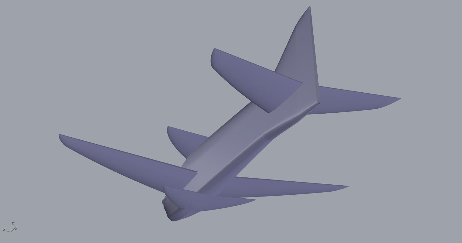
So as title suggests nothing new in design ,I was watching some vids of the WC in Aus and got inspired by the good flying planes there.
I think this set up presents extremely well in the air .
The set up will have a contra prop (I'm flirting with the DxG one)
I also have some new ideas about various components we'll see..
This post can have step by step all the procedure from drawing to finished plane ,I hope some people can learn something and hopefully I can get motivated and learn from others too.
So here are some pics from the 3d drawing.
If there is interest from people I'll keep posting.
Cheers !
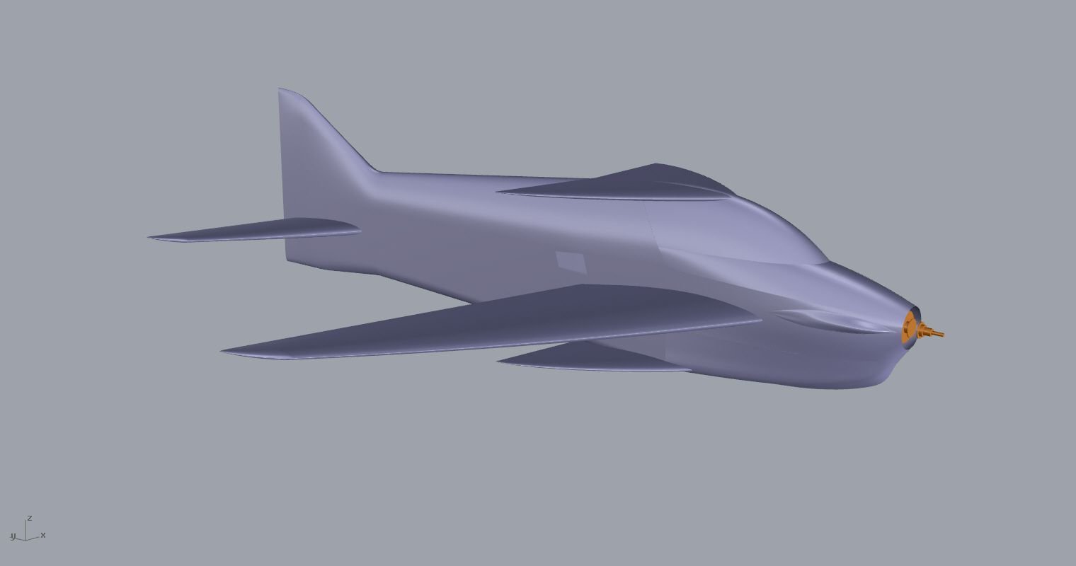
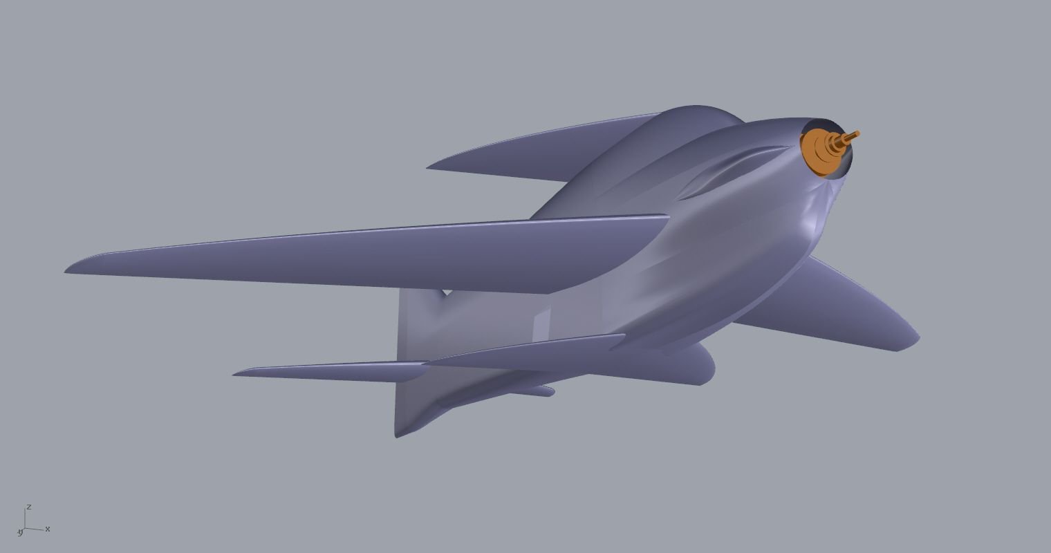
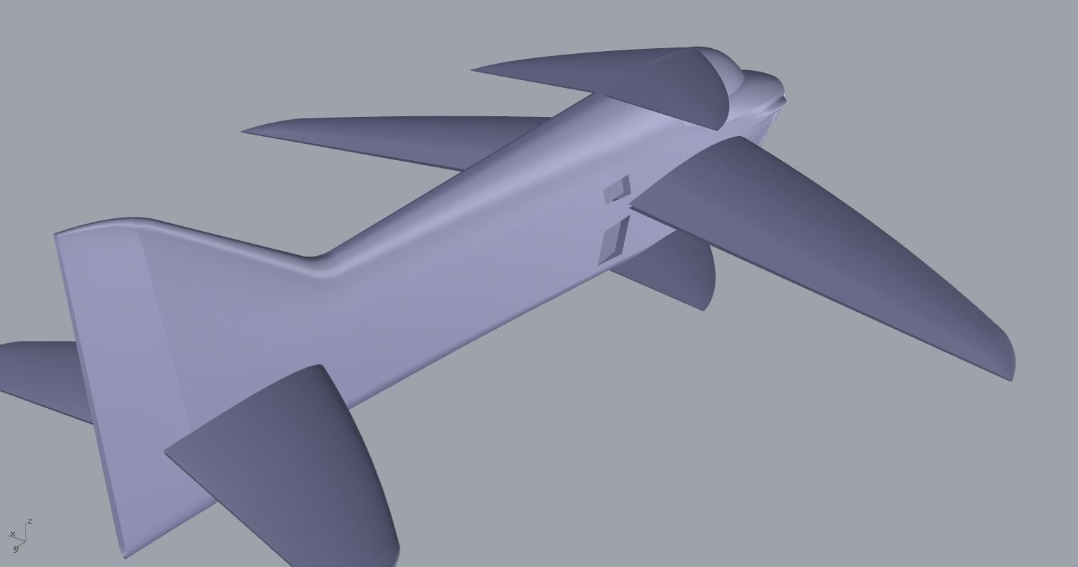
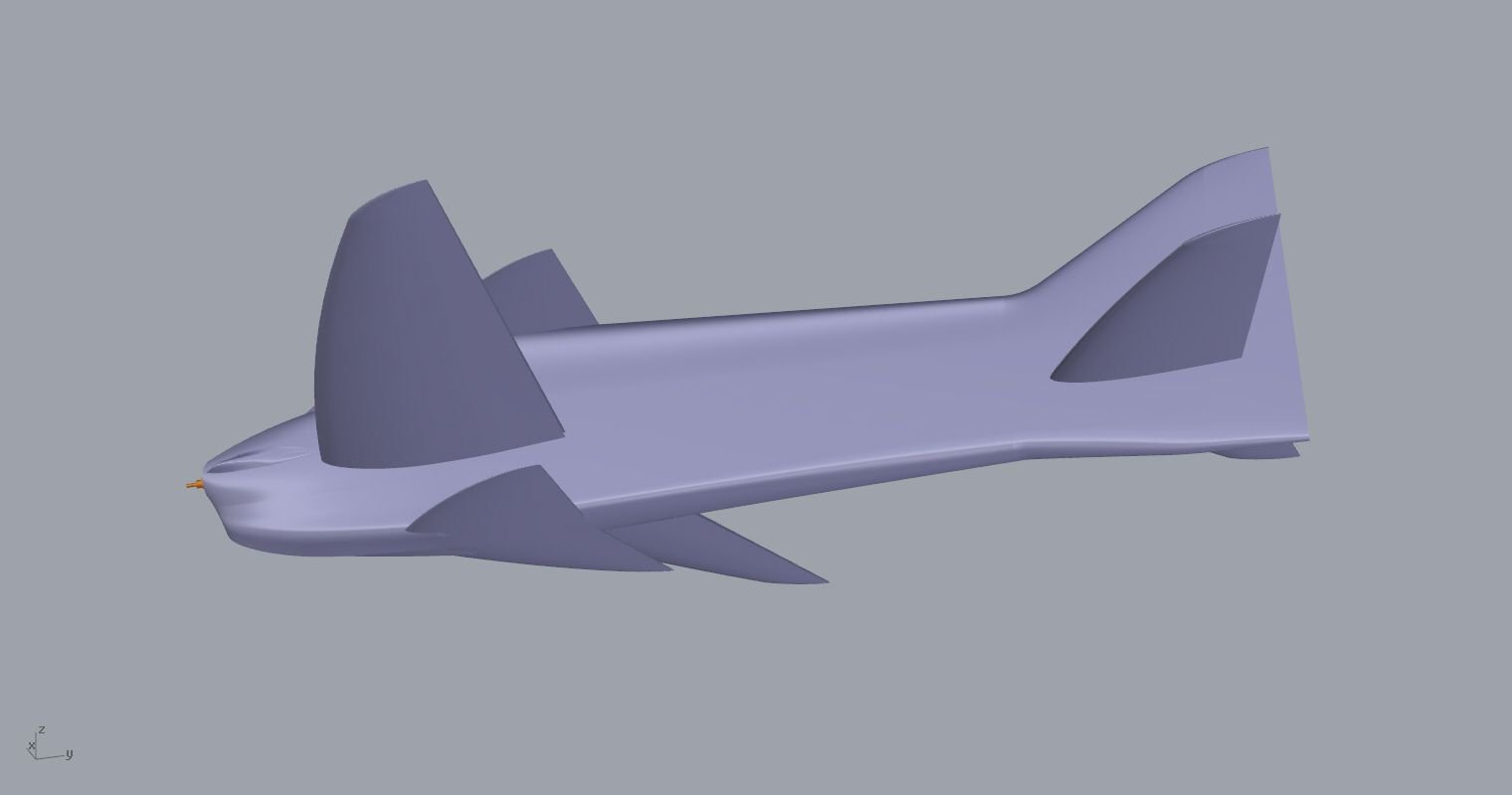


Last edited by Elias Sopeoglou; 09-18-2024 at 11:37 PM.
#3

Thread Starter
Join Date: Apr 2006
Location: thessaloniki, , GREECE
Posts: 165
Likes: 0
Received 5 Likes
on
4 Posts
Hi thanks !
Can you please explain more about your thought ? I have noticed most of the new designs keep the canopy forward. I usually try to keep the canopy relatively forward but not too close to the prop to leave room for the flow to accelerate cleaner.
Also any side area in front of center of lift is destabilizing yaw axis.
Is it about more knife edge lift you are considering ?
I hope we can trigger some nice aerodynamics discussions..
Elias
Last edited by Elias Sopeoglou; 09-19-2024 at 10:14 PM.
#4
Senior Member
I think having more side area would definitely help with knife edge performance .
Having the canopy forward would also help with slow speed stability as it is producing more lift than a rearward one.
The destabilising effect in yaw due to Centre of Pressure can be mitigated by rudder size and area above and below the thrust line.......
regards
Having the canopy forward would also help with slow speed stability as it is producing more lift than a rearward one.
The destabilising effect in yaw due to Centre of Pressure can be mitigated by rudder size and area above and below the thrust line.......
regards
#5

Looks to be very “generic” as drawn. What is the reason for the two canalisers? Having flown a number of single canaliser models I have always found them more than sensitive enough on rudder. I flew a twin canaliser design for a couple of seasons and found it so sensitive on rudder that it was very difficult to get and keep it in yaw trim. The bottom canaliser is vulnerable to being stood on either by the pilot or helper when ground handling as well.
The only advantage I can see for the double canaliser is if using IC power, it’s a place to mount a second airbrake. Other than that it’s a liability.
The only advantage I can see for the double canaliser is if using IC power, it’s a place to mount a second airbrake. Other than that it’s a liability.
#6
Senior Member
Looks to be very “generic” as drawn. What is the reason for the two canalisers? Having flown a number of single canaliser models I have always found them more than sensitive enough on rudder. I flew a twin canaliser design for a couple of seasons and found it so sensitive on rudder that it was very difficult to get and keep it in yaw trim. The bottom canaliser is vulnerable to being stood on either by the pilot or helper when ground handling as well.
The only advantage I can see for the double canaliser is if using IC power, it’s a place to mount a second airbrake. Other than that it’s a liability.
The only advantage I can see for the double canaliser is if using IC power, it’s a place to mount a second airbrake. Other than that it’s a liability.
Watching CPLR and Antonin fly their OREKAS at the world championships in Australia I can honestly say this kind of design has the best tracking stability than any other .
#7

Thread Starter
Join Date: Apr 2006
Location: thessaloniki, , GREECE
Posts: 165
Likes: 0
Received 5 Likes
on
4 Posts
I would comment that the double cans have the double effect of making lift in NE positions with no need to enlarge the fuselage more.In a mid wing design as this is it makes perfect sense to want to ''keep'' the air in the fuselage at the bottom part as well.You can think of the cans as winglets on a very very.. VERY low aspect ''wing'' ,the fuselage. Having more and more side area especially in the front is not the best solution for F3A as we are flying in cross wind all the time and it drifts our planes. Further more large cans especially two of them act as normal wings making possible to have smaller main wing with a positive effect on rolling and snapping maneuvers ,an ingenious solution by an ingenious man..
Last edited by Elias Sopeoglou; 09-22-2024 at 11:35 PM.
#8

Thread Starter
Join Date: Apr 2006
Location: thessaloniki, , GREECE
Posts: 165
Likes: 0
Received 5 Likes
on
4 Posts
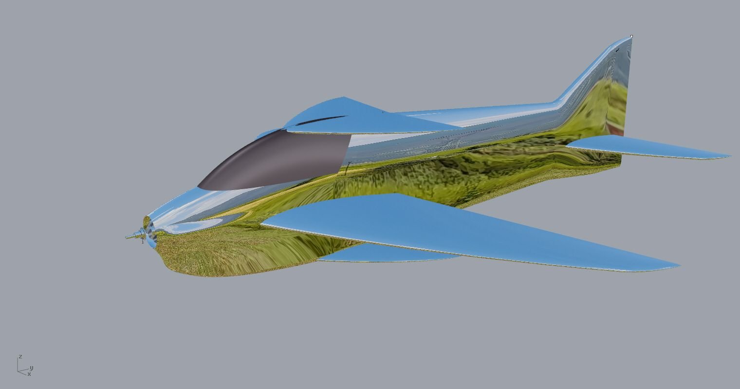
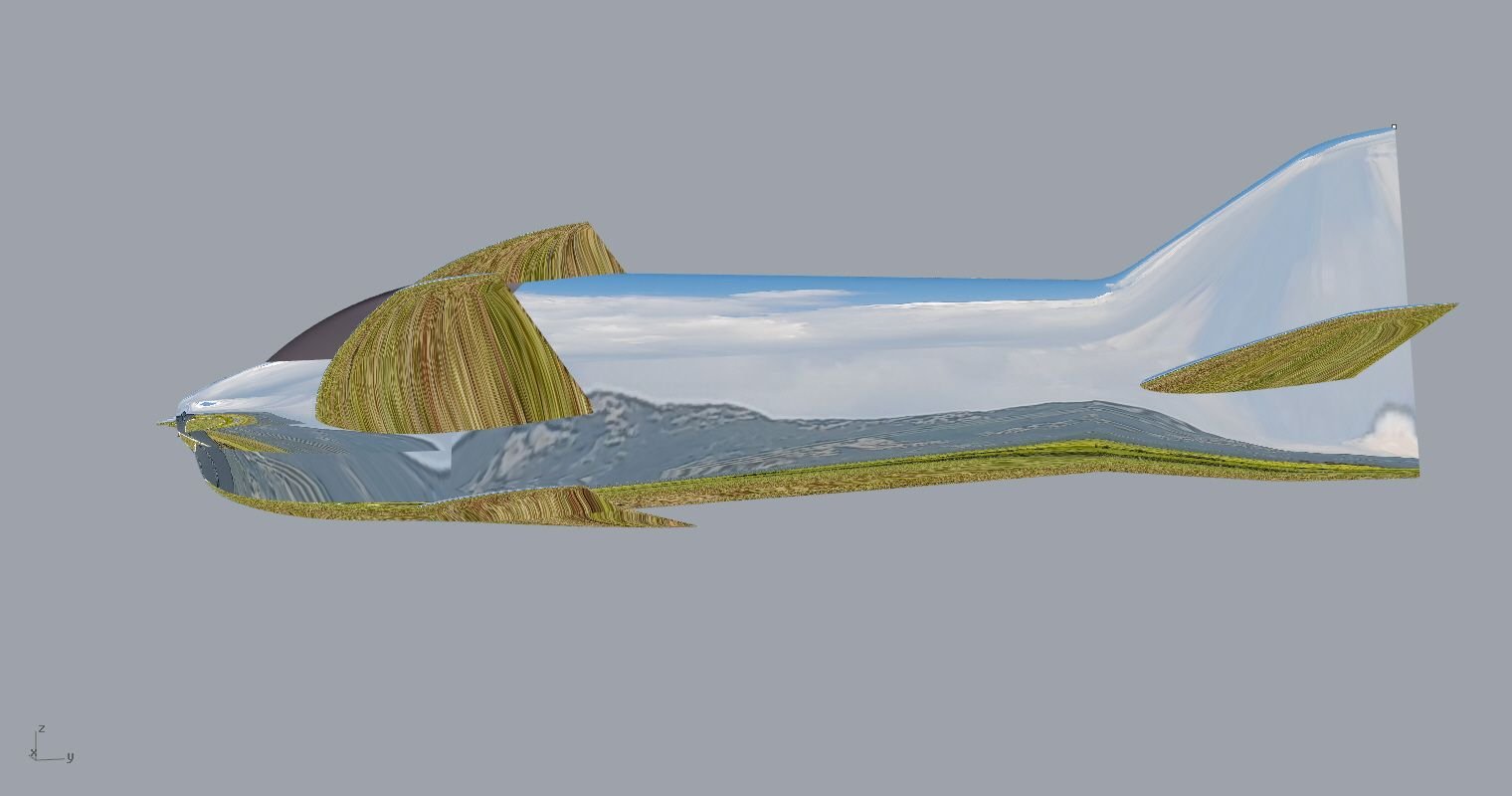
Did a few changes ,actually opened the canopy curve a bit to the front ,I think this way I can have only the canopy and top can as removable pieces and not need to cut the fuse ,it will be more rigid and will have a clean cut line of the two volumes this way. Rounded the aft section of the fuse a bit ,looks less ..sqare ish.Also redesigned the side air inlets.


Last edited by Elias Sopeoglou; 09-23-2024 at 06:22 AM.
#10
Senior Member
Better Elias but I would still suggest you move the canopy further forward for true lift genaration at slow speeds.
This would also help with balancing the rotational inertia which will make the snap recovery easier.
At the last world championships I watched Christophe do the best Rolling circle of the event but snaps not so good........although snaps are very much open to interpretation ....[img]images/icons/icon7.gif[/img]
#11

Thread Starter
Join Date: Apr 2006
Location: thessaloniki, , GREECE
Posts: 165
Likes: 0
Received 5 Likes
on
4 Posts
Better Elias but I would still suggest you move the canopy further forward for true lift genaration at slow speeds.
This would also help with balancing the rotational inertia which will make the snap recovery easier.
At the last world championships I watched Christophe do the best Rolling circle of the event but snaps not so good........although snaps are very much open to interpretation ....[img]images/icons/icon7.gif[/img]
This would also help with balancing the rotational inertia which will make the snap recovery easier.
At the last world championships I watched Christophe do the best Rolling circle of the event but snaps not so good........although snaps are very much open to interpretation ....[img]images/icons/icon7.gif[/img]
Maybe I didnt understand correct what your are trying to say.
Aerodynamically I think there will be tons of side lift with this fuse and crosswind flying is more crucial.
Thank you either way ! I think canopy looks just fine (and sexy :-)
#12
Senior Member
If i understand correct ,you suggest snap rolls will stop faster and cleaner because of the extra 10-15 grams from a bigger canopy ? If you calculate the equal in wing tip weight this would be something like 0,3gr or less.
Maybe I didnt understand correct what your are trying to say.
Aerodynamically I think there will be tons of side lift with this fuse and crosswind flying is more crucial.
Thank you either way ! I think canopy looks just fine (and sexy :-)
Maybe I didnt understand correct what your are trying to say.
Aerodynamically I think there will be tons of side lift with this fuse and crosswind flying is more crucial.
Thank you either way ! I think canopy looks just fine (and sexy :-)
What I meant was more fuselage lift means less wing lift required.... smaller wing.......better snap performance.
Either way your design does look ' sexy'......
#13

Thread Starter
Join Date: Apr 2006
Location: thessaloniki, , GREECE
Posts: 165
Likes: 0
Received 5 Likes
on
4 Posts
Ok now i get it . I would expect that the fuse needs quite alot of aoa in that axis to produce mesurable lift ,unless you have a fuse shape like a two seater experimental airplane. My bet is on for those two huge cans actually im tempted to enlarge them a bit more..
Last edited by Elias Sopeoglou; 09-28-2024 at 09:28 AM.
#14

Thread Starter
Join Date: Apr 2006
Location: thessaloniki, , GREECE
Posts: 165
Likes: 0
Received 5 Likes
on
4 Posts
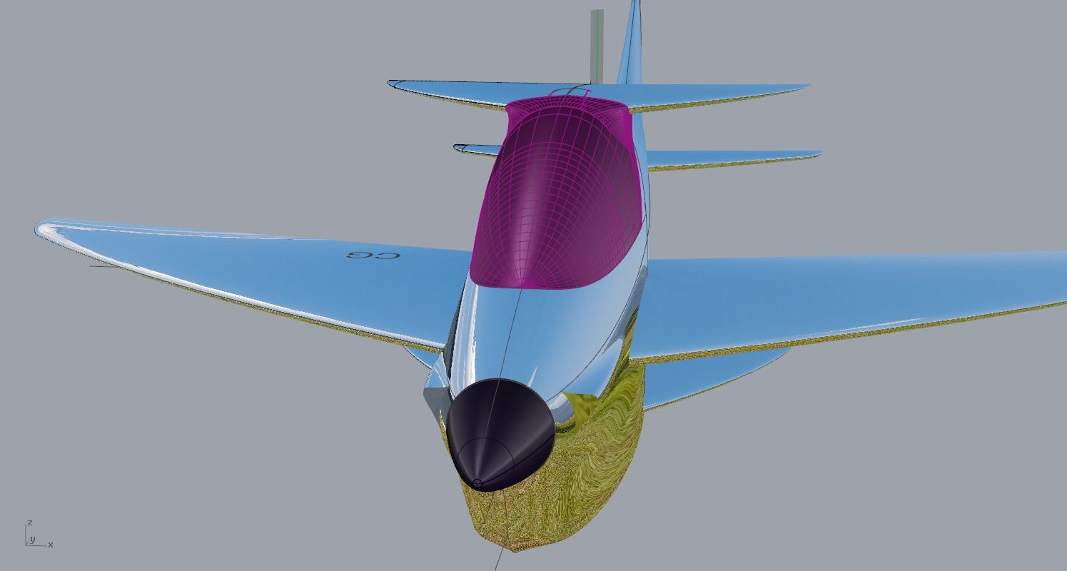
Did a few changes including the widening of the fuse and a bit more swept at the wing ,despite being quite significant they are barely noticable looking at the 3d drawing pics.
Finished the top Can blending and canopy split lines ,actually it was more difficult than I would think ,but looks like it went just fine.
Now have to finish the bottom can and I'm ready to wrap this up !
eyes hurt..
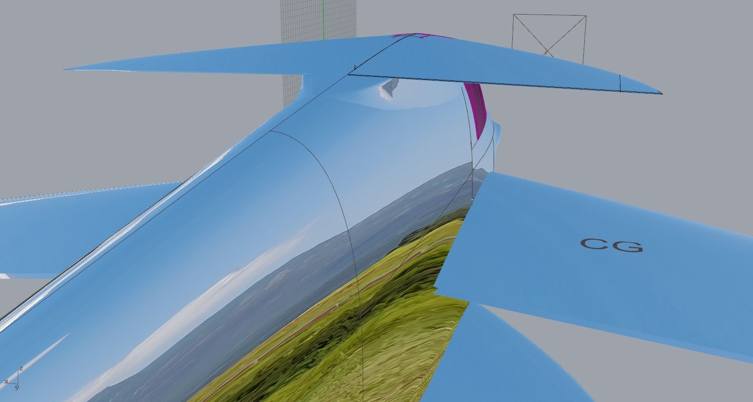
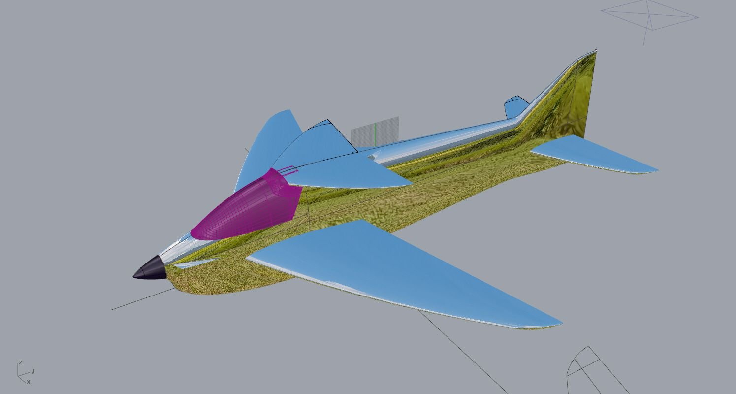
Finished the top Can blending and canopy split lines ,actually it was more difficult than I would think ,but looks like it went just fine.
Now have to finish the bottom can and I'm ready to wrap this up !
eyes hurt..


#15

Thread Starter
Join Date: Apr 2006
Location: thessaloniki, , GREECE
Posts: 165
Likes: 0
Received 5 Likes
on
4 Posts
Lower can finished and that wraps up the cad drawing ! Pheeww !
I think it turn out quite nice,
Now will start the moulds drawings .Parts must have clean separation lines , more cad work...
I have a question about cooling outlets ,I've seen quite a few versions of them on several planes.How large should they be ? from What I understand something like 2X (10x40mm) should be enough.
Also about contra systems ,what do you suggest ? I like the DG system because of the simplicity of design with less parts compared to the belt systems.
Here are some pics
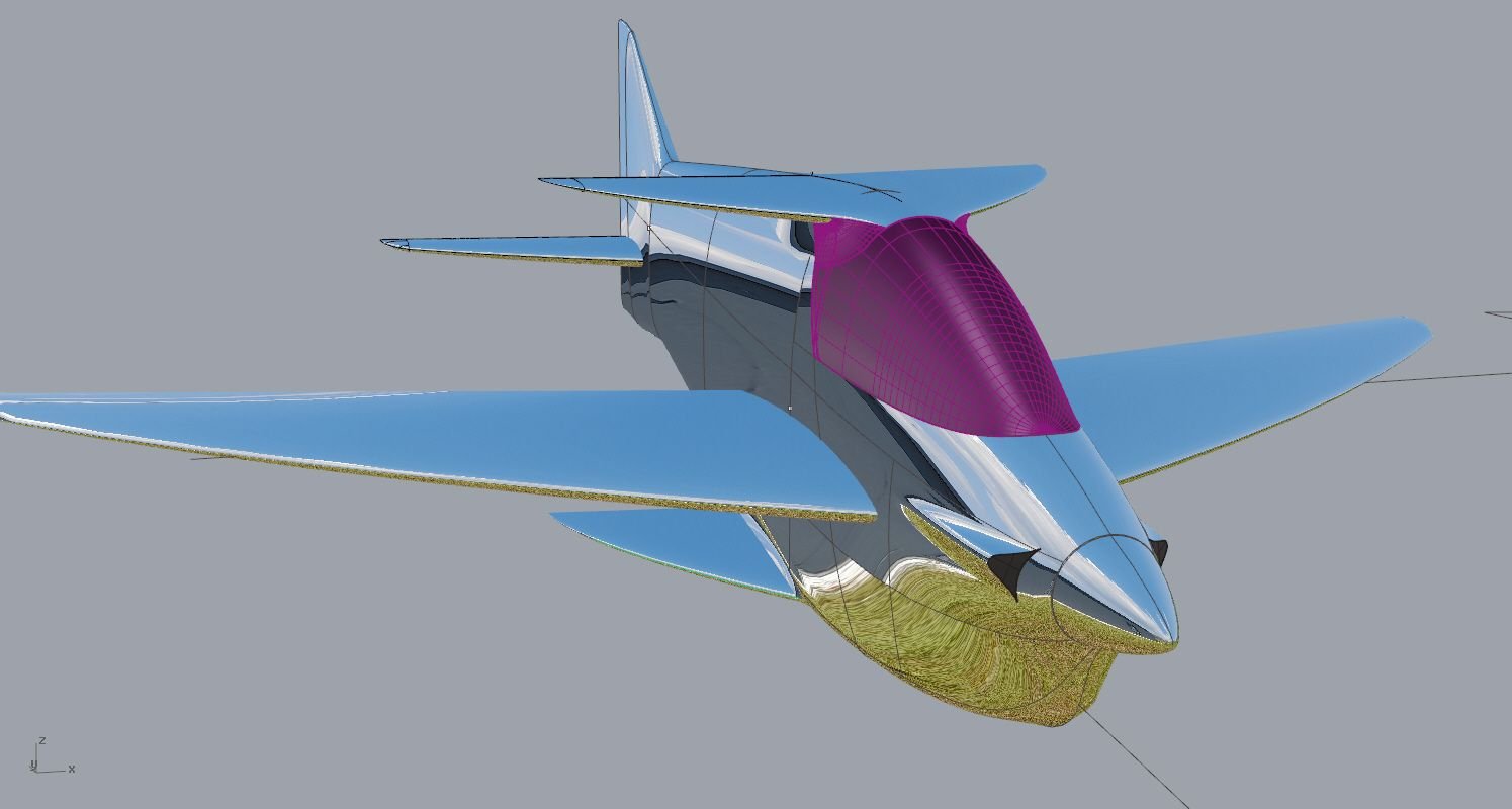
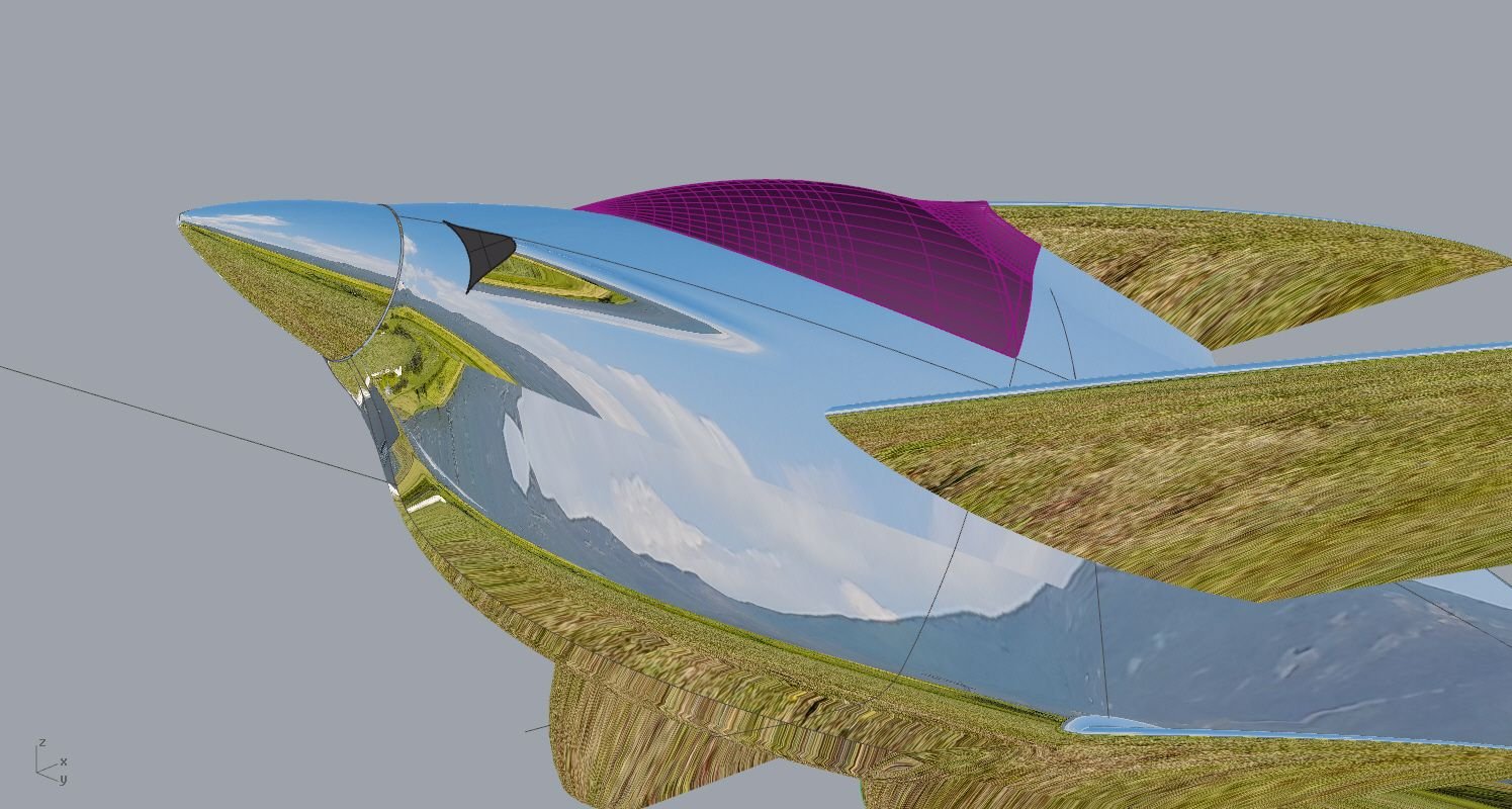
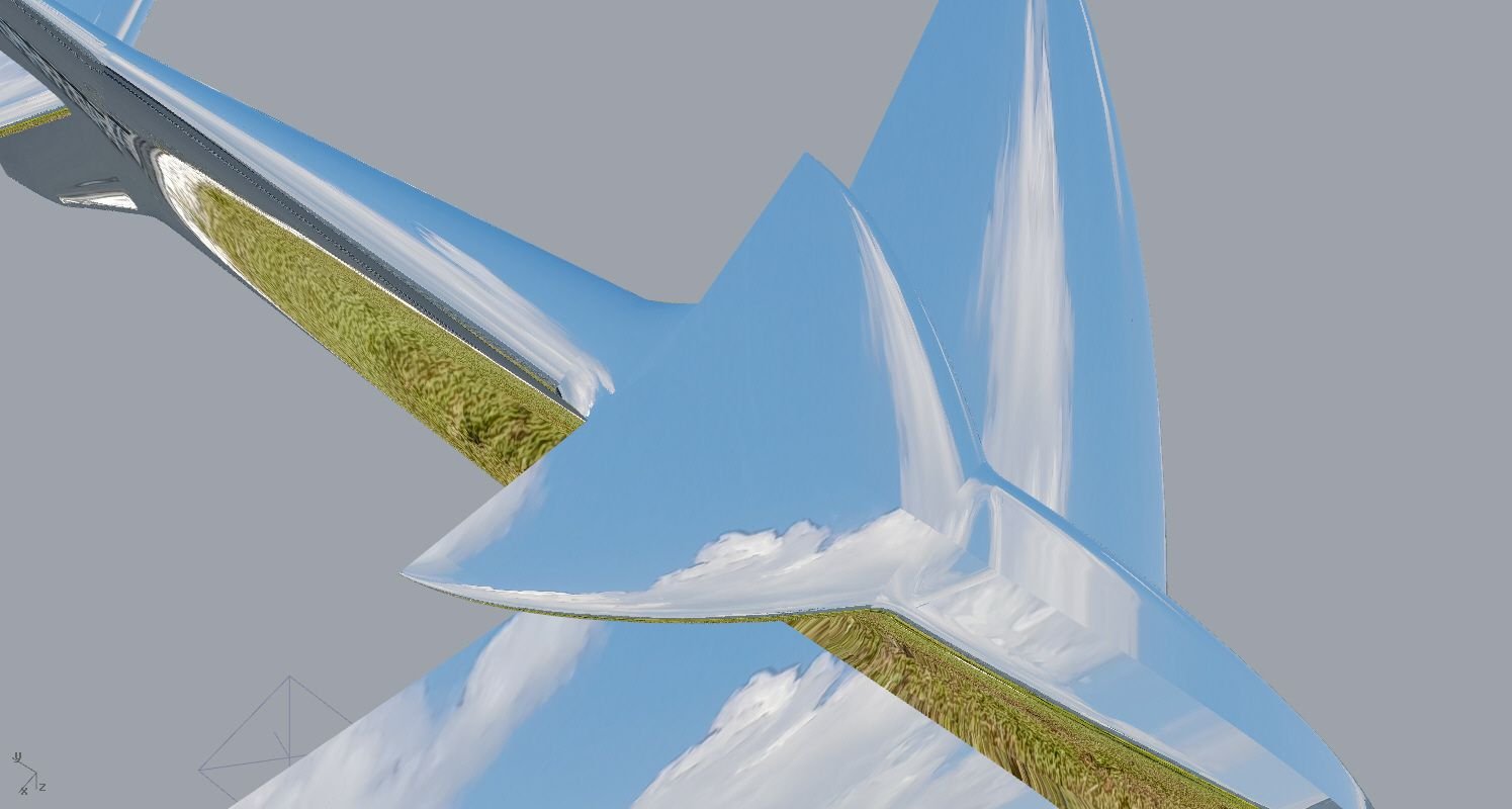
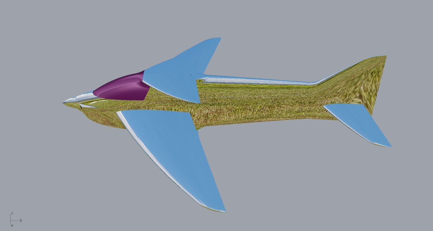
It's a wrap !
I think it turn out quite nice,
Now will start the moulds drawings .Parts must have clean separation lines , more cad work...
I have a question about cooling outlets ,I've seen quite a few versions of them on several planes.How large should they be ? from What I understand something like 2X (10x40mm) should be enough.
Also about contra systems ,what do you suggest ? I like the DG system because of the simplicity of design with less parts compared to the belt systems.
Here are some pics


It's a wrap !
#16
Senior Member
lower can finished and that wraps up the cad drawing ! Pheeww !
I think it turn out quite nice,
now will start the moulds drawings .parts must have clean separation lines , more cad work...
I have a question about cooling outlets ,i've seen quite a few versions of them on several planes.how large should they be ? From what i understand something like 2x (10x40mm) should be enough.
Also about contra systems ,what do you suggest ? I like the dg system because of the simplicity of design with less parts compared to the belt systems.
Here are some pics


it's a wrap !
I think it turn out quite nice,
now will start the moulds drawings .parts must have clean separation lines , more cad work...
I have a question about cooling outlets ,i've seen quite a few versions of them on several planes.how large should they be ? From what i understand something like 2x (10x40mm) should be enough.
Also about contra systems ,what do you suggest ? I like the dg system because of the simplicity of design with less parts compared to the belt systems.
Here are some pics


it's a wrap !
The following users liked this post:
Ricardo M. (Yesterday)


