


Welcome to Club SAITO !
 09-12-2016, 04:29 AM

My Feedback: (102)

Join Date: Dec 2001
Location: Colonial Beach, VA
Posts: 20,370
Likes: 0
Received 25 Likes
on
25 Posts
I try to take pictures of the Tachometer readings and am careful to label them, it's very difficult to get a picture of the engine and the tach, it would take three hands. The TNC is difficult to see in the afternoon sun so I keep a yellow legal pad close for those times. Waste of time, probably, fun time, yes. This is a Saito FA .40a turning a Bolly 9.5x6, not enough prop in my book.
 09-12-2016, 04:30 AM
Senior Member

Just my 2 cents worth on "drawer guide" thrust measuring tools....
I opted for some really nice multi-ball drawer sliders. My test were 20 to 40% less than what others had quoted using different methods.
So I tried pushing down on reliable electronic scales, and sure enough, my readings for the same combo were suddenly 20 to 40% higher. Mind you, these were done using electric. Back to back using the same motor, prop, ESC and battery on both test rigs.
The important part here was that it illustrated to me was that even if you can't "feel" any perceptible drag on your horizontal rig, there maybe more drag there than you realise, and your static figures may be quite a bit less that 'absolute'.
I then opted for some 'linear' bearings - but haven't gotten around to building a new test rig to use them yet. If I ever do, I'll run back to back to back tests to see what sort of correlation I get.
And yes - while what you get during a bench test can vary a fair bit to what you get during actual flight, at least is can serve as some sort of a guide. Apples to apples kinda thing. i.e. if something is pulling 1/2 a kilo more thrust just by switching from, say, a 7x5 prop to an 8x6, it's pretty easy to see which one produces more thrust. But...at what cost? In electrics, you can pretty easily see which one draw more Amps and induces more battery sag over time.
I/C engines seem to work the opposite way - over-prop them and they'll just slow die in rpm and either stall the engine.. or stall the aircraft.
With electrics, the more you ask of them, they more they will try to deliver. The ESC/battery/motor will keep on trying to to give - until something burns out. Usually the weakest link in the chain. Be it the motor, the ESC, or the battery.
All the above guff said - *any* test bench can still provide a level of comparison between changing one thing in an engine/prop/(fuel) combo, providing only one thing is changed at a time, and the test bench and environmental conditions remain basically the same throughout each testing process.
How absolutely 'correct' that measurement is does have a bit to do with any friction of all the measuring components involved doing a kg/lb pull/push test.
When testing anything v's anything else, I try to keep things as fair and constant as possible. i.e. change only one item, and don't test today when it's 15 deg C and humidity is 80%...then run the other test tomorrow when it's 30 deg C in the shade with 60% humidity.
It's all E=MC^2 in the end...
BJ
09-12-2016, 04:36 AM
My Feedback: (102)
Join Date: Dec 2001
Location: Colonial Beach, VA
Posts: 20,370
Likes: 0
Received 25 Likes
on
25 Posts
I have two sets of "trucks" from under a skate board, for all practical purposes the wheels turn friction free. Attaching them to my PSP set up requires a solution that alludes me so far.

 09-12-2016, 05:40 AM
Here is a take off on what is known as the ballistic pendulum. How about a double triangle frame structure with the lower horizontal legs used to mount the platform mounting the engine. The platform would be connected to an electronic (fishing) scale, and restrained by a safety cable. The upper four arms would connect to a cross tube which is supported by a pair of low friction ball bearings, such as we use for our engines. The rod on which the tube rotates could be supported be a second set of fixed triangle legs. The thrust of the engine would pull the platform pivoting it around the bearing supported upper cross tube. The longer the upper legs of the triangle the less influence the friction of the bearings would be. Whadya think?
09-12-2016, 05:57 AM
Senior Member
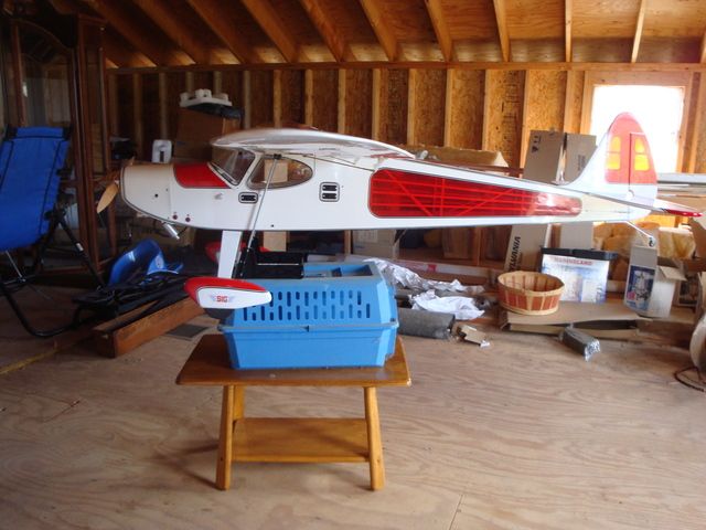
110" WS, 14# 4 oz weighed with this.

Flies like a Cub on steroids at 1/2 throttle!.
Last edited by SrTelemaster150; 09-12-2016 at 07:41 AM.
09-12-2016, 06:00 AM
Senior Member
Here is a take off on what is known as the ballistic pendulum. How about a double triangle frame structure with the lower horizontal legs used to mount the platform mounting the engine. The platform would be connected to an electronic (fishing) scale, and restrained by a safety cable. The upper four arms would connect to a cross tube which is supported by a pair of low friction ball bearings, such as we use for our engines. The rod on which the tube rotates could be supported be a second set of fixed triangle legs. The thrust of the engine would pull the platform pivoting it around the bearing supported upper cross tube. The longer the upper legs of the triangle the less influence the friction of the bearings would be. Whadya think?
09-12-2016, 06:35 AM


Join Date: Jun 2009
Location: Melbourne, AUSTRALIA
Posts: 1,505
Received 0 Likes
on
0 Posts
09-12-2016, 06:50 AM
Sincerely, Richard
AMA 861960
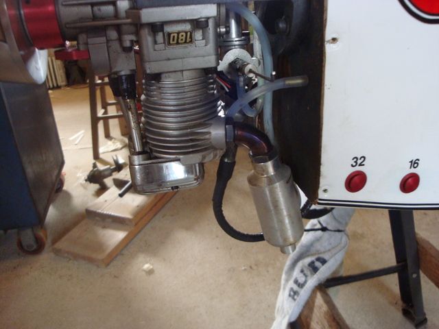
Club Saito #635; Saito 56, 100, 120abc, 130T, 180
09-12-2016, 07:01 AM
Join Date: Jun 2009
Location: Melbourne, AUSTRALIA
Posts: 1,505
Received 0 Likes
on
0 Posts
PS - my F180 and Turbines tried to do the same.
Skeery chit when you get to that "uh-oh... it's gonna TAKE OFF!" moment - but there's no airframe around it/them...
BJ
Skeery chit when you get to that "uh-oh... it's gonna TAKE OFF!" moment - but there's no airframe around it/them...
BJ
09-12-2016, 07:30 AM
09-12-2016, 07:45 AM
Senior Member
09-12-2016, 07:55 AM
That's a classic I really wondered how the guy kept from eating the engine! When I was just out of high school my best buddy took a job in a pipe shop making fire suppression equipment. He built me a test stand I still wish I had. It was a tripod of welded 2 1/2 inch thick wall pipe with a steel platform on top, no R/C engine could move that baby!
09-12-2016, 02:23 PM
Senior Member
Still waiting on the Rascal 168 to be released. Thinking an FG-61T http://www.horizonhobby.com/product/...gine-saieg61ts would be the perfect engine for it.
09-13-2016, 03:28 AM
My Feedback: (102)
Join Date: Dec 2001
Location: Colonial Beach, VA
Posts: 20,370
Likes: 0
Received 25 Likes
on
25 Posts
The Xoar 16x6 arrived yesterday, I believe those greenish, blue circles are for balancing. I can't be certain, just a thought. I have several Xoars now and about half of them have those.
09-13-2016, 04:10 AM
Senior Member
I have a 22 x 10 XOAR and it has the same thing. If I ever break that prop I'll section it & see if there is a metal pin or other weight under the plastic.
09-13-2016, 04:10 AM

Pssstt barry i wish i could write this smaller and keep it quiet you know.Dave's just fessed up to BUYING an apc prop,jeez,it does'nt get any better than this.I knew the boys would'nt throw all their toys outta the cot and if they had i got a secret weapon,just whistle long dead granny up to give us all a big tablespoon of castor oil,i'll have castrol r
09-13-2016, 04:35 AM
My Feedback: (102)
Join Date: Dec 2001
Location: Colonial Beach, VA
Posts: 20,370
Likes: 0
Received 25 Likes
on
25 Posts
My thoughts exactly. The hole is exactly right for the 1.25, the APC's are coming with .25" holes, I think I have a Bennett Built drill with a .25" pilot.
Pete, I am very sure the APC's will not be fruitful and multiply.
Pete, I am very sure the APC's will not be fruitful and multiply.