


Welcome to Club SAITO !
 03-20-2019, 09:21 AM


[.
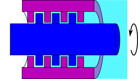
Yep, move water, grain, sawdust, oil etc up, sideways , you name it. Same exact principle as used in the Fox, MG, John Deere etc. Also known as a "Scroll" seal, it relies on a HELIX to move the media in a single direction, depending on the rotational direction.
The Labyrinth seal uses parallel, closely fitted grooves to provide a seal. Many variations but a distinct difference. The Archimedes type seal is helical or spiral, The Labyrinth elements are parallel or concentric
There are face type equivalents for both types as well. The helical face seal is found often as a seal in older dishwashers and some water pumps like the old "Hale�" firefighting pumps. The Labyrinth face type scroll seals are used as mentioned in high speed applications to minimize heat build up. They use the Archimedean principle just the same. Not a Labyrinth.
As I said, I have machined BOTH types of seals. From cars to machine spindles.
 03-20-2019, 09:27 AM
...Archimedes-Type Rear Crankshaft Oil Seals
Perhaps the most annoying source of oil leaks in older British sports car engines is the mechanical oil slinger/seal arrangement designed as the primary rear crankshaft seal. The theory of this archimedes-principle seal, is that the spiral grooves at the back of the crank fit with only a slight clearance to the stationary upper and lower oil control surfaces. As the crankshaft rotates, the action of the reverse oil control threads against the flat sealing surfaces draws the excess oil back into the hollow cavity next to the rear bearing where the oil drains harmlessly back to the oil pan.
In reality, this seal arrangement works well as long as minimum clearances are maintained. A slight amount of leakage is inevitable when the engine is shut down. This residual oil drains through a small hole in the bell housing and should not amount to more than a few drops escaping on to your driveway!
Since the oil control threads and the sealing surface are not supposed to wear, few workshop manuals offer detailed instructions on the fitting of these seals nor quote specific clearances. In studying engineering drawings for the T-series crankshaft and rear main upper seal, factory clearances can be calculated to .0053″ minimum to .0088″ maximum. The MGA Workshop Manual specifies a total clearance of.003″ to .006″. Although the T-series spec. seems overly generous, the MGA spec. appears more reasonable and can be considered a guide for all applications.
The sealing surfaces (and, to a lessor extent, the oil control threads) will wear if the rear main bearings become excessively worn or if the block alignment becomes distorted. Leakage problems can also result from inaccurately refitting the replaceable sealing surfaces used on many British sports cars. Jaguar and TR2-4A used replaceable upper and lower seals, Austin-Healey 100-4 and MG TC-TD-TF used only a replaceable upper seal while the MGA and 6 cylinder Healey incorporated sealing surfaces cast integrally with both the block and rear main cap.
In renewing this critical seal, a number of alternative techniques can be employed. Perhaps the most foolproof and effective method is to have your block and the sealing surfaces line-bored by a competent machine shop. By carefully measuring bearing saddle dimensions and/or the diameter of the oil control threads, correct oil seal diameters can be determined. This is a fairly expensive operation but is the only way to restore non-replaceable sealing surfaces. (MGA owners take note, as this is a common problem!)
Replaceable seals can be hand-fitted with care and considerable patience. The crankshaft and main bearings should first be installed and checked for proper clearance using “Plastigauge”, available from any automotive machine shop. Also, check to be certain the crank rotates freely and has proper end float, then remove crank and prepare to trial fit bolt-on sealing plates. On MG TC-TD-TF blocks, remove the two small dowel pins, as these would effectively prevent any adjustment in the location of the seal. Install seal loosely, using appropriate gasket and gasket cement. Apply a thin film of engineer’s bluing (the thicker type sold in squeeze tubes is easier to work with) to the sealing face. With the seal fixing bolts slightly loose it should be possible to snug and center the seal against the crank. After tightening up the seal, torque the lubricated crank assembly to full spec. Now, carefully rotate the crank once or twice before removing the crank once again to inspect the contact pattern on the seal. The ideal situation is to adjust the seal so that you are left with a very thin film of engineer’s bluing on the sealing surfaces. Particular attention should be paid to the upper sealing surface on the block as these are most subject to wear and are consequently most critical.
In some cases, it may be necessary to remove some material from the parting face of one or both seals. This must be done carefully; lay sandpaper on a dead flat surface or pane of glass to help insure accuracy . It may be necessary to remove and refit the crank five to six times to insure that you have achieved a correct fit. A certain degree of light contact is not generally objectionable, particularly with the replaceable aluminum seals, as these will bed-in as soon as the engine is started. Heavy contact that makes the crank difficult to rotate could, however, cause serious problems. The small dowel pins originally used with the T-series seals are not really required and their reinstallation can cause distortion and/or a shift in location of the plate. If these pins are reinstalled, recheck your work once again.
Once the seals have been installed, checked and rechecked, assembly can continue but may require that the crank be removed once again in order to install connecting rods and pistons. (Remember folks, patience is the ultimate virtue!) Last, but not least, particular care should be exercised in installing the oil pan together with all appropriate gaskets and seals. While assembling these components apply silicone gasket cement to clean dry surfaces.
Having hand fitted and determined with all certainty that you have achieved a correct fit, your rear main seal should be nearly 100% drip free. A last word of advice: be sure that your crankcase breathers are clean and free of obstruction and that your gearbox first motion shaft seal is in good order. A problem in either can otherwise mask over a job well done.
Last edited by Jesse Open; 03-20-2019 at 09:43 AM.
03-20-2019, 12:05 PM
My Feedback: (1)
first, the engine will be mounted upside down,, so I figured the Lobes and Tappet would get more oil this way before the Tappets round the Lobes. because I figured if I had put the Barb on the right side of the case the Lobes would push some oil out the Barb "before" the Tappet round the Lobes,, hear too, if in the future I happen to mount the engine on it's side the Barb will be pointing up, again allowing more oil on the Lobes and Tappets before the Tappets round the Lobes,
rather right or not that was my thoughts on that, any comments on this ?????????????
but it probably makes no difference LOL
Jim
 03-20-2019, 01:18 PM

My Feedback: (102)

Join Date: Dec 2001
Location: Colonial Beach, VA
Posts: 20,370
Likes: 0
Received 25 Likes
on
25 Posts
I was thinking mounting 90 degrees to the right, thinking a little more my thought is that it would flood the engine with oil if mounted to the right.l. I dunno somebody will,have to try it.
PS, I have the APC 12 x 6's and a new tach to finish testing the Saito 50.
I dunno somebody will,have to try it.PS, I have the APC 12 x 6's and a new tach to finish testing the Saito 50.
Last edited by Hobbsy; 03-20-2019 at 01:28 PM.
03-20-2019, 02:22 PM
boy that�s quite the little 50.
 03-20-2019, 03:58 PM
Another very strongly built car. IIRC , The engine was derived from a tractor engine.
I only owned and drove a single Triumph car. That was a 1967 Spitfire. Nothing like the bigger Triumphs, it was the only Brit car I was happy to see go away. I traded it for a 1968 Royal Enfield Interceptor MK 1a.
Loved that moto--/--!
Saito content:
Glowgeek,
Muffler left today vi usps priority mail. You should have it Friday. If not, email me I have tracking number.
I included a bit of SWAK thread sealer to use between the adapter and the head. Also an aluminum washer for the pipe flange to adapter seal.
The SWAK works great for me. You must let it sit 24 hours after assembly before running.
I guess that about squares me here.
Good luck.
Last edited by Jesse Open; 03-20-2019 at 04:07 PM.
03-20-2019, 05:32 PM
Another very strongly built car. IIRC , The engine was derived from a tractor engine.
I only owned and drove a single Triumph car. That was a 1967 Spitfire. Nothing like the bigger Triumphs, it was the only Brit car I was happy to see go away. I traded it for a 1968 Royal Enfield Interceptor MK 1a.
Loved that moto--/--!
Saito content:
Glowgeek,
Muffler left today vi usps priority mail. You should have it Friday. If not, email me I have tracking number.
I included a bit of SWAK thread sealer to use between the adapter and the head. Also an aluminum washer for the pipe flange to adapter seal.
The SWAK works great for me. You must let it sit 24 hours after assembly before running.
I guess that about squares me here.
Good luck.
RE Spitfire: My dad had a late 60's Triumph GT6+ , MK2. Man was that thing loud! I loved the noise cuz I could hear him coming home from miles away, gave me time to pop in a breath mint, wash my hands and hide my cigs.....lol
He traded that obnoxious thing in on a new Datsun 240Z and busted me smoking behind the house the day he brought it home....lol Upgrade for him, downgrade for me.
Oh, how does SWAK differ from a TFE paste like Tplus2?
Last edited by Glowgeek; 03-20-2019 at 05:34 PM.
03-20-2019, 06:23 PM
My Feedback: (1)
Jim
Last edited by the Wasp; 03-21-2019 at 08:26 AM.
03-21-2019, 12:48 AM


This car could take the wrinkles out of your forehead
A very pretty car mike i've restored a couple over the years my dream weekend car long ago was an austin healey 3000.With no mechanical skills to speak of i guess i wished to add another two cylinders and 50% more woe if things went pear shaped.After reading gary's post on pumps i've figured out why most of the oil fell out of the engine round the bellhousing.If you got your tr3 and sim english cars of that era as a direct new car import to the states then the under chassis and bodywork would usually last a few years without major repairs.Over here we mostly got 'grey' imports that had years of use on salted roads in england and arrived at the shop in need of rust repairs and painting.After a few beers at night,and with the lights off in the panel shop,you could sneak up on one of those and listen to the metal mice munching all the bare metal inner panels,the rust coloured metal they left behind was called metal mice poo.
Dave,i remember years ago you experimenting with different cc breather locations and my memory is that it was inconclusive? i have a rear vent fa115 think i did the bearings twice on that engine so far.When i reassemble any saito i smear auto transmission fluid over all parts and when stripped again the pushrods and cam gear are always wet,smells like castor to
your thoughts on breather location and even breather recirculation to the carb cheers
Last edited by Rudolph Hart; 03-21-2019 at 12:57 AM.
03-21-2019, 03:06 AM
My Feedback: (102)
Join Date: Dec 2001
Location: Colonial Beach, VA
Posts: 20,370
Likes: 0
Received 25 Likes
on
25 Posts
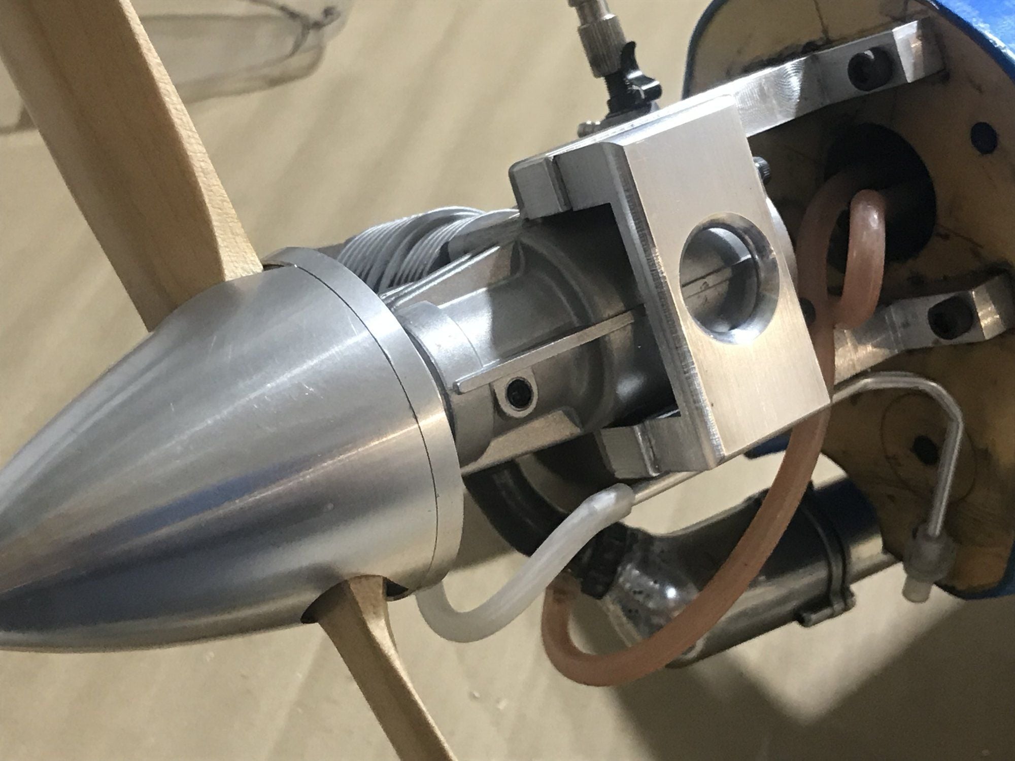
Dave, I forgot, this photo is the other reason I put the Barb on the right side,, click it to enlarge,,
Jim
Attachment 2263790
Jim
Attachment 2263790
03-21-2019, 03:27 AM
My Feedback: (102)
Join Date: Dec 2001
Location: Colonial Beach, VA
Posts: 20,370
Likes: 0
Received 25 Likes
on
25 Posts
This car could take the wrinkles out of your forehead
A very pretty car mike i've restored a couple over the years my dream weekend car long ago was an austin healey 3000.With no mechanical skills to speak of i guess i wished to add another two cylinders and 50% more woe if things went pear shaped.After reading gary's post on pumps i've figured out why most of the oil fell out of the engine round the bellhousing.If you got your tr3 and sim english cars of that era as a direct new car import to the states then the under chassis and bodywork would usually last a few years without major repairs.Over here we mostly got 'grey' imports that had years of use on salted roads in england and arrived at the shop in need of rust repairs and painting.After a few beers at night,and with the lights off in the panel shop,you could sneak up on one of those and listen to the metal mice munching all the bare metal inner panels,the rust coloured metal they left behind was called metal mice poo.
Dave,i remember years ago you experimenting with different cc breather locations and my memory is that it was inconclusive? i have a rear vent fa115 think i did the bearings twice on that engine so far.When i reassemble any saito i smear auto transmission fluid over all parts and when stripped again the pushrods and cam gear are always wet,smells like castor to
your thoughts on breather location and even breather recirculation to the carb cheers Smileys X 10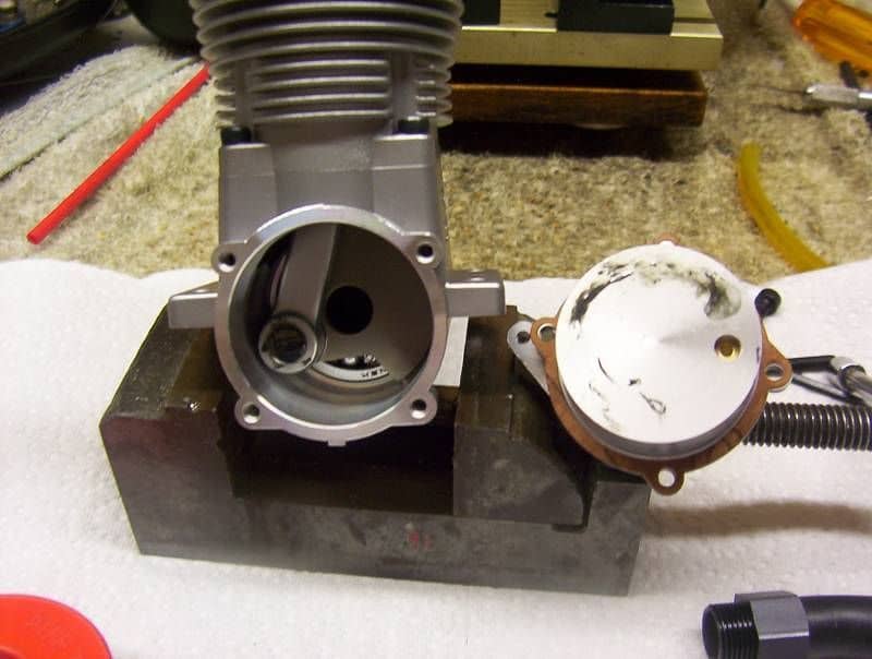
Pete, here is my Saito 115 right out of the box
03-21-2019, 04:06 AM
Good morning Pete, that was my high compression 150 that I used to experiment, I first placed the vent on the flat side of the cam housing and blocked the rear vent. This will probably earn me another 10,000 word lecture, but here goes. No oil ever came out of the vent of the cam box. Next I put an additional vent on the other flat of the cam box along with a check valve, (out) on the rear vent and ran a line to the left side vent on the cam box thinking oil would flow out through the check valve forward to,the left side of the cam box and then out the right side of,the cam box. Again, no oil flowed anywhere. There was plenty of oil, the fuel was Wildcat Premium Plus with 18% 80/20 blend. So I blocked the cam box vents and oil happily flowed out rear vent again. I eventually replaced the cam box and lived happily ever after, never to move another vent. I am of the opinion that no matter how much others preach it, it simply doesn't accomplish anything. That's my take on it and as the old lady in W. Va. said, I'm stickin to it. Smileys X 10
Pete, here is my Saito 115 right out of the box
Smileys X 10Pete, here is my Saito 115 right out of the box
Interesting Dave. For your experiment was the engine mounted upright, inverted or side? Also, was the rear bearing open on both sides?
03-21-2019, 04:40 AM
Jim, Fret not, your vent will work fine, even if you wind up with a bit more oil in the cam chest , no harm there. Also, the water vapors will be well vented. I can send you a pair of check valves. Put the intake in the old rear rear vent and the outlet in the new front vent. You can watch the very evenly spaced slugs of oil and air moving down the vent line, positively and regularly.
Pete, The Archimedes screw seal on the rear of those BMC engines (and some John Deere and Fox engines) worked just about like the fellow said in the article. If there was a lot of blowby or a plugged case vent, they would blow oil badly!
Regarding the Saito vent; I get good oil evacuation oil from the front vent in EVERY case. The good part is knowing that oil is flowing well to the cam box area where oiling cuts wear substantially. Not a "one shot' it never works" inconclusive test here.
Adding the check valves make it very well measured and enables the use of longer vent pipes.
I started doing this BEFORE Saito moved these vents .If it did not work, I would have quit doing it over 35 years ago and I doubt Saito would do it at all.
Not quite a thousand tests but perhaps more than a thousand flights. I didn't start doing it 10 years before I was born and I just gave a response in less than 10,000 words. So unlike others, no exaggeration here
03-21-2019, 04:45 AM
Good morning Pete, that was my high compression 150 that I used to experiment, I first placed the vent on the flat side of the cam housing and blocked the rear vent. This will probably earn me another 10,000 word lecture, but here goes. No oil ever came out of the vent of the cam box. Next I put an additional vent on the other flat of the cam box along with a check valve, (out) on the rear vent and ran a line to the left side vent on the cam box thinking oil would flow out through the check valve forward to,the left side of the cam box and then out the right side of,the cam box. Again, no oil flowed anywhere. There was plenty of oil, the fuel was Wildcat Premium Plus with 18% 80/20 blend. So I blocked the cam box vents and oil happily flowed out rear vent again. I eventually replaced the cam box and lived happily ever after, never to move another vent. I am of the opinion that no matter how much others preach it, it simply doesn't accomplish anything. That's my take on it and as the old lady in W. Va. said, I'm stickin to it. Smileys X 10
Pete, here is my Saito 115 right out of the box
Smileys X 10Pete, here is my Saito 115 right out of the box
Maybe it varies. Does not seem like an assembler in the factory would be acting independently of instructed procedures and removing it or leaving the shields that the bearing manufacturer shipped them with. Assuming Saito is buying rather then making the bearing.
interesting to note. Looks like grease on the crankpin and tracking on the rear cover. I use an assembly oil from Boca on my reassemblys.
Whats the deal about using atf to clean cases? Never tried it. Brake Kleen is my go to for general cleaning during repairs. But dosent touch the baked on external patina most e bay cast offs are sporting though. Don't
want a gallon of that nasty carb dip solvent going bad in the can for fifty bucks. Sounds like you just heat atf and drop it in? New to me. I live under a rock.
Oh for the love of Saito!
03-21-2019, 04:46 AM
All of my saitos are cam housing vented and use an open rear bearing. The oil starts coming out of the vent within a few seconds after startup and advancing to wot.
Last edited by Glowgeek; 03-21-2019 at 04:55 AM.
03-21-2019, 05:34 AM
Best way to keep engine clean is never to run them in a plane
Last edited by Jesse Open; 03-21-2019 at 05:38 AM. Reason: Added quote
03-21-2019, 06:26 AM
My Feedback: (102)
Join Date: Dec 2001
Location: Colonial Beach, VA
Posts: 20,370
Likes: 0
Received 25 Likes
on
25 Posts
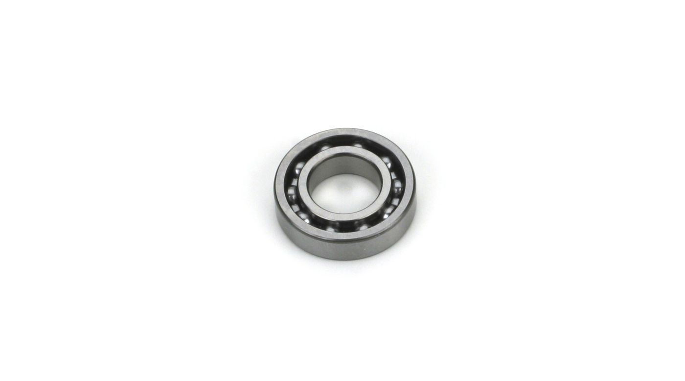
Here is a sampling of the stock Saito rear bearings 125-a, FA 40-a and the FA 30, the little one is the only one with a shield.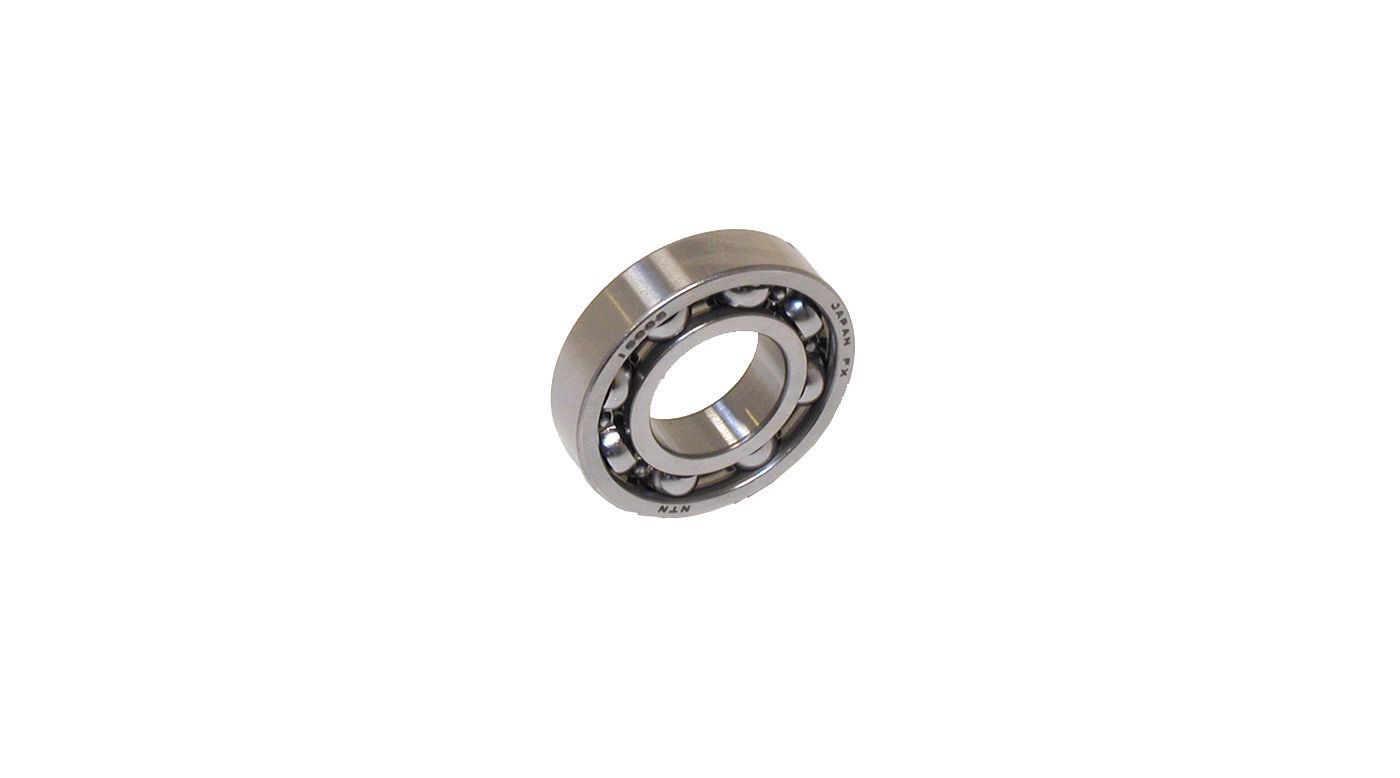
Saito 125 rear bearing
Saito FA 40-a rear bearing
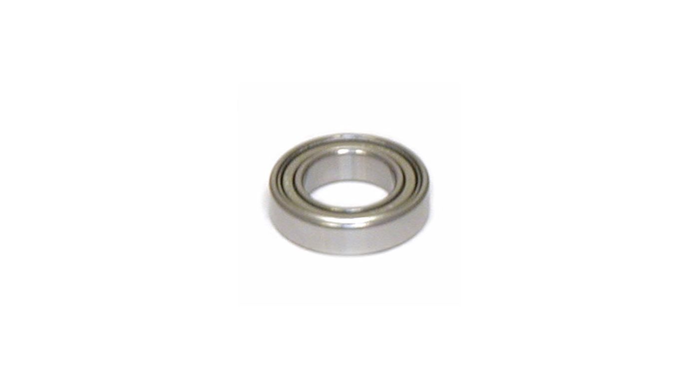
Saito 30 rear bearing
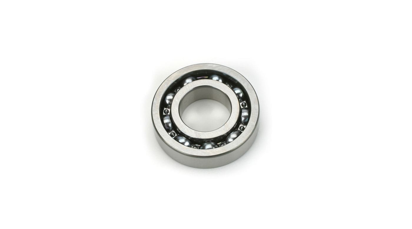
And even though I don't have one a 115 rear bearing. I think it is safe to say most are open.
Saito 125 rear bearing
Saito FA 40-a rear bearing
Saito 30 rear bearing
And even though I don't have one a 115 rear bearing. I think it is safe to say most are open.
 03-21-2019, 07:26 AM
Jim,
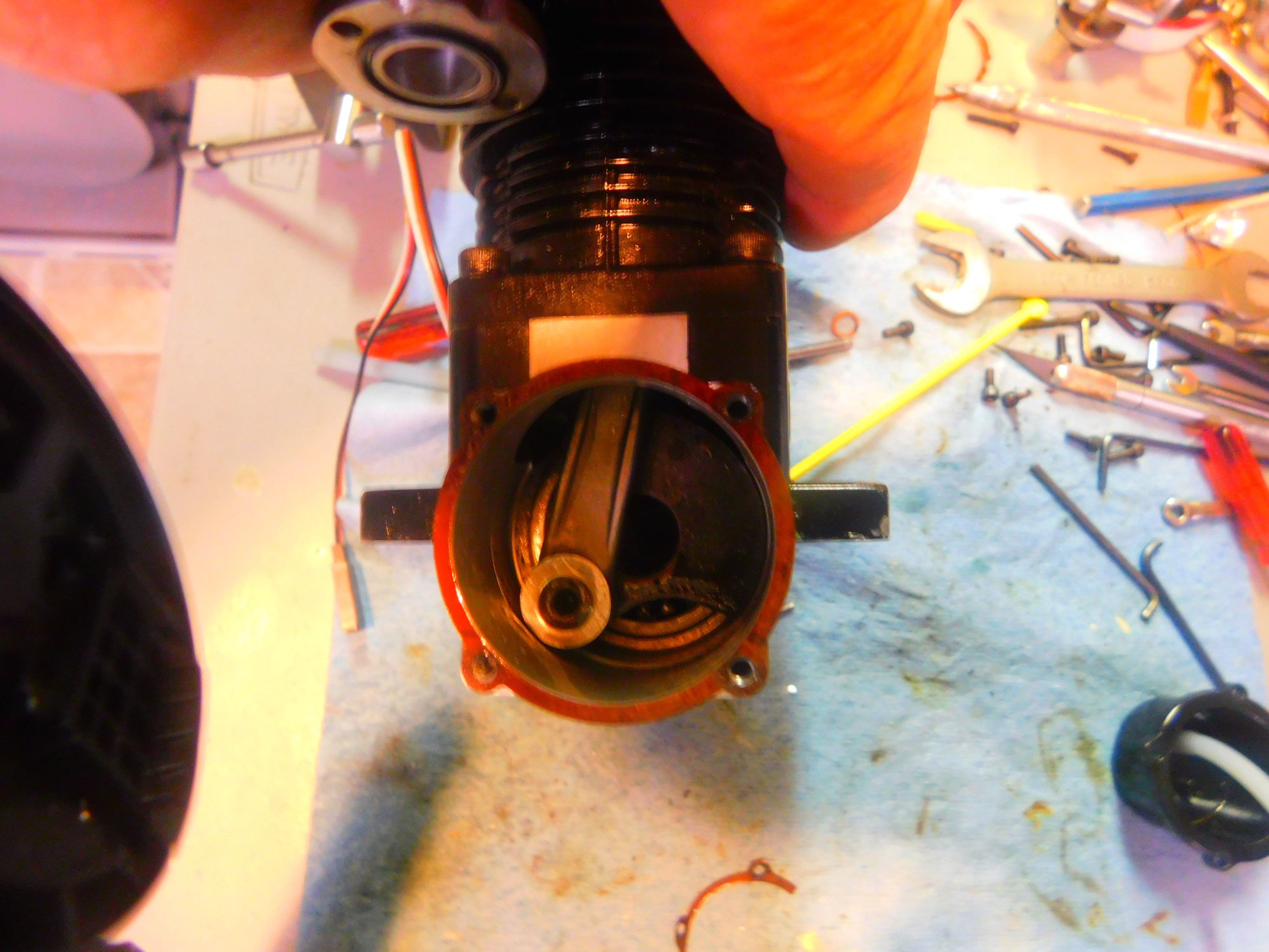
Here's a pic of an FA-82 that has seen at least 10 years of hard flying. Note the vent is on the low side of the cam housing and the factory vent that had been at the front bottom is now plugged. Rest assured 10 years worth of oil easily found its way out
Original bearings etc, runs like new.