


Welcome to Club SAITO !
 12-10-2021, 05:57 AM


Thanks for the reply.
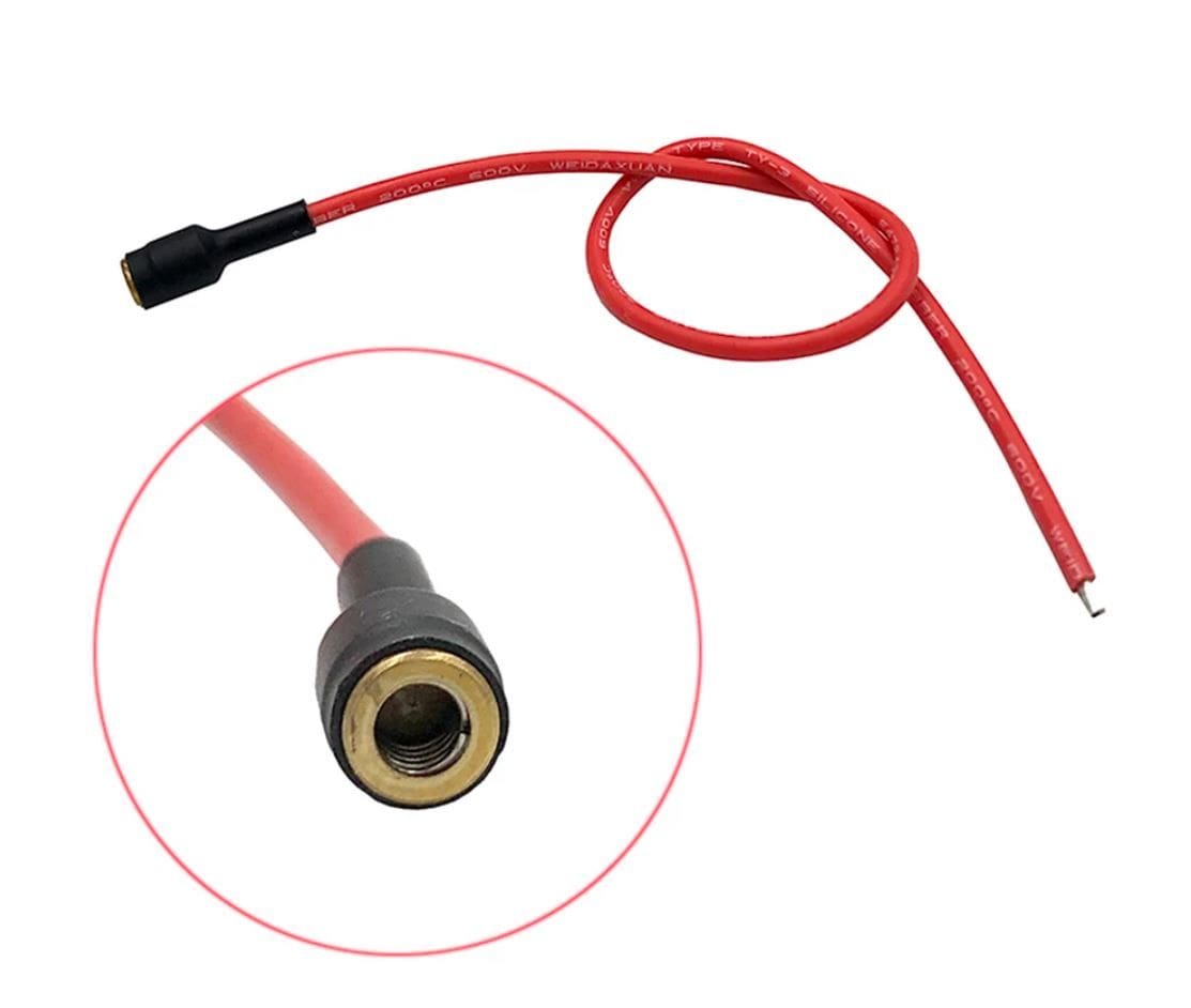
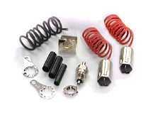
I just found one that is close to the photo I posted above. The one I posted above is brass with a steal ball that snaps against the glowplug stem. The spring on the outside is what puts pressure on the steal ball to hold it on the glowplug stem.
This is the one I just found: RCEXL Pipe head Plug Clip Heat Engine Type Plug Clip For Glow System Ignition
It is close but it has a spring inside to grab the glowplug stem. I ordered two so I'll give them a try.
If anyone knows any source for the one above please let me know.
Thanks,
Evan
I'll get a couple of those and check them out. They come from aliexpress.com and are only $3.80 for two.
Yessir, just like the OS pattern. They hold very firmly indeed. Too bad there aren't more plugs wth screw on terminals like those on Enya plugs.
No muss, no fuss and nothing unsightly. Very reliable, low resistance connection.
Last edited by Jesse Open; 12-10-2021 at 06:01 AM.
 12-10-2021, 08:41 AM
My Feedback: (149)
Morning Dave, Would be very interested in how you power your remote connectors. Have a lithium powered RCATS ignitor, and was sure it would have enuf "umph" to lite 2 plugs. Did call mfg who suggested not designed for multi plug operation. Do you use multiple ignitors for your installations?
T-man49 in Al
T-man49 in Al
 12-10-2021, 07:02 PM
Here is a Glow Driver that I built. The original plans came from RC Modeler in Jan 2002 by Stan Evans. I came across it by accident.
I have a South Hertz Glow driver from the UK and it works very well. I have the South Hertz in a Great Planes Tiger Moth with a Saito 91 and there is plenty of room for it and the battery. I have a very large D size battery NiCd running the South Hertz in the Tiger Moth. The South Hertz one uses a PIC (Programmable Integrated Circuit) and some other electronics to sense the resistance in the glow plus and energize it when needed. I believe the PIC is just used to sense the joy stick position to enable it. To enable it you move the throttle to full and then idle to turn it on. The throttle position does nothing else but initially enable it. Resistance adjusted by a POT.
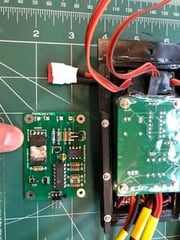
So the one that I made is very similar to the South Hertz version except for No PIC. The way I designed the one below is with just solid state electrics. It senses the resistance on the glow plug and will energize it as needed. To set the resistance you adjust it with the POT and that is all. This version uses through hole components so the overall size of the board is larger than it needs to be but it is still quite small. If i use surface mount and redesign the board I could probably make it about 1/4 the size it is now So maybe about 1"x1".
I used the version in the photos below in an Ultra Stick with an FA-80T.
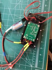
I flew the Ultra Stick with the FA-80T but its not powerful enough for the ultra stick so I replaced it with an FA-91 but it was a good test bed for the glow driver. I made a hatch with my 3D printer to mount dual cards, one each for each cylinder and one POT for each cylinder.
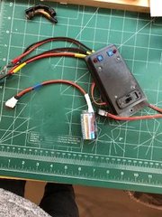
This one has a C size 5000 milliamp Nicd, two POTS and two LEDs. When it ignites a glow plug the LEDs light up.
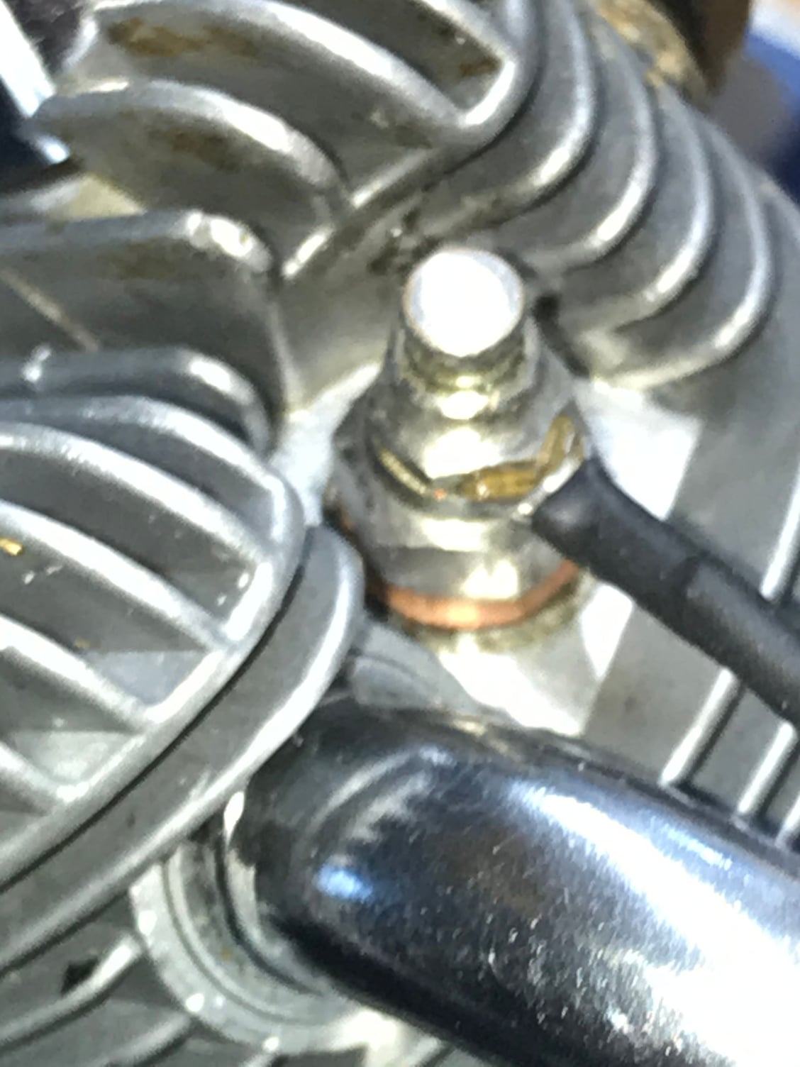
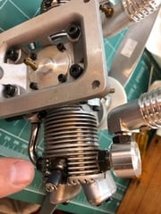
This shows one of the Glow Plug adapters i made out of brass rod with a set screw to hold it tight to the plug stem.
Below shows the bottom of the two boards in the hatch. The board is powered by the receiver battery but the glow plus is powered by the 1.2 volt 5000 milliamp C Nicd.
The board itself does not draw much power. I have run it with a LIFA battery 7.2 volts tied directly into my receiver battery.
The photo also shows an unmounted card without the wires. As you can see there is even room here to tighten it up the space on the circuit board a little but if i convert it to surface mount it will be must smaller.
I have compared it with another board that uses a PIC to sense the resistance and this one is much faster to re-energize the glow plus especially when the engine is idling because there is no code running. It's all solid state.
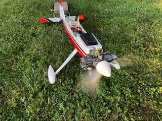
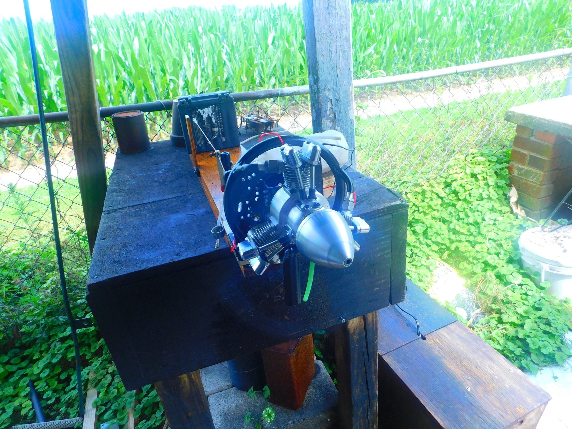
Below is the FA-80T mounted and running with the dual glow driver. The idle was quite low for a glow twin and it also helped to keep each cylinder from going out.
It works. :-)
I now have the FA-91 on it and it has way more power.
I just acquired and FA-100T that I may try on the Ultra Stick as well with the same setup.
Thanks for looking,
Evan
I have a South Hertz Glow driver from the UK and it works very well. I have the South Hertz in a Great Planes Tiger Moth with a Saito 91 and there is plenty of room for it and the battery. I have a very large D size battery NiCd running the South Hertz in the Tiger Moth. The South Hertz one uses a PIC (Programmable Integrated Circuit) and some other electronics to sense the resistance in the glow plus and energize it when needed. I believe the PIC is just used to sense the joy stick position to enable it. To enable it you move the throttle to full and then idle to turn it on. The throttle position does nothing else but initially enable it. Resistance adjusted by a POT.
So the one that I made is very similar to the South Hertz version except for No PIC. The way I designed the one below is with just solid state electrics. It senses the resistance on the glow plug and will energize it as needed. To set the resistance you adjust it with the POT and that is all. This version uses through hole components so the overall size of the board is larger than it needs to be but it is still quite small. If i use surface mount and redesign the board I could probably make it about 1/4 the size it is now So maybe about 1"x1".
I used the version in the photos below in an Ultra Stick with an FA-80T.
I flew the Ultra Stick with the FA-80T but its not powerful enough for the ultra stick so I replaced it with an FA-91 but it was a good test bed for the glow driver. I made a hatch with my 3D printer to mount dual cards, one each for each cylinder and one POT for each cylinder.
This one has a C size 5000 milliamp Nicd, two POTS and two LEDs. When it ignites a glow plug the LEDs light up.
This shows one of the Glow Plug adapters i made out of brass rod with a set screw to hold it tight to the plug stem.
Below shows the bottom of the two boards in the hatch. The board is powered by the receiver battery but the glow plus is powered by the 1.2 volt 5000 milliamp C Nicd.
The board itself does not draw much power. I have run it with a LIFA battery 7.2 volts tied directly into my receiver battery.
The photo also shows an unmounted card without the wires. As you can see there is even room here to tighten it up the space on the circuit board a little but if i convert it to surface mount it will be must smaller.
I have compared it with another board that uses a PIC to sense the resistance and this one is much faster to re-energize the glow plus especially when the engine is idling because there is no code running. It's all solid state.
Below is the FA-80T mounted and running with the dual glow driver. The idle was quite low for a glow twin and it also helped to keep each cylinder from going out.
It works. :-)
I now have the FA-91 on it and it has way more power.
I just acquired and FA-100T that I may try on the Ultra Stick as well with the same setup.
Thanks for looking,
Evan
12-10-2021, 07:08 PM
My Feedback: (149)
Hey Lonnie, That certainly looks good to me for on board. Really like the simplified programing - about my speed LOL! Have a small unfinished mini plane with a 60t up front - believe a .56 was popular in it. Was hopeful for a remote set up as expect a weight situation.
Many Thanx and have a great Holiday X-MAS season.
T-man49 in Al
Mike 723
Many Thanx and have a great Holiday X-MAS season.
T-man49 in Al
Mike 723
12-10-2021, 07:45 PM
My Feedback: (149)
Hello Evan, Your work looks very well engineered and crafted and purposeful. Have moved to CDI for my larger twins - a 182T and 270T specifically for low rpm and smooth running. Do appreciate your input, as always looking for options.
Have a great weekend
T-man49
Mike 723
Have a great weekend
T-man49
Mike 723
12-11-2021, 02:18 AM
Senior Member

Morning Dave, Would be very interested in how you power your remote connectors. Have a lithium powered RCATS ignitor, and was sure it would have enuf "umph" to lite 2 plugs. Did call mfg who suggested not designed for multi plug operation. Do you use multiple ignitors for your installations?
T-man49 in Al
T-man49 in Al
 12-11-2021, 04:43 AM
Hi,
Per the threads above here is a link to a video of my Home made glow driver.
I'm no electrical engineer but this was a very fun project and in the end it worked. I got some help from the guys on the BadCaps web site. https://badcaps.net/forum/showthread.php?t=71680
What is really amazing to me is these days you can use a web site to design the board and even test it on-line to make sure it works as intended. Then you push a button and in a week or less you have 5 PCBs in the mail ready for you to solder up and the cost is nothing. I have heard that some companies will even place the components on the board so it's ready when you get it. I have not tried that yet.
Thanks for looking,
Evan
12-11-2021, 05:00 AM
Senior Member
I experienced a near miracle this AM, I found two of the tiny O-rings that go in the end of the Saito spray bars. I had mentioned a few days ago of a spray bar O-ring that had hardened and broken into several pieces. I managed to get all the pieces out, then installed one of the finds, it was as easy as pushing it in there and it popped into place. I have an extra. The HS needle slides in and out with a slight, smooth drag. This 150 carb gasket kit may contain it.: https://www.hobbyplastic.co.uk/index...20jojqp6sa5i01

A great find. I installed one in a big block spray bar.
A great find. I installed one in a big block spray bar.
Last edited by 1200SportsterRider; 12-11-2021 at 05:22 AM. Reason: Spelling
 12-11-2021, 06:49 AM

I experienced a near miracle this AM, I found two of the tiny O-rings that go in the end of the Saito spray bars. I had mentioned a few days ago of a spray bar O-ring that had hardened and broken into several pieces. I managed to get all the pieces out, then installed one of the finds, it was as easy as pushing it in there and it popped into place. I have an extra. The HS needle slides in and out with a slight, smooth drag. This 150 carb gasket kit may contain it.: https://www.hobbyplastic.co.uk/index...20jojqp6sa5i01
A great find. I installed one in a big block spray bar.
A great find. I installed one in a big block spray bar.
 12-11-2021, 11:29 AM
12-11-2021, 02:54 PM
12-11-2021, 03:22 PM
12-11-2021, 11:29 AM
12-11-2021, 02:54 PM
12-11-2021, 03:22 PM
My Feedback: (27)
It might be for an 80 then because I have several of them. I was hoping it would be the size Jim was looking for. I just checked the bore size again with dial calipers and it is 1.050 at the bottom.
12-11-2021, 07:30 PM
My Feedback: (1)

looks to be the 65 cylinder sniff sniff tears in eyes.
calculator here
https://www.towerhobbies.com/conversion-calculator.html
specs here
Specifications
Jim
Last edited by the Wasp; 12-11-2021 at 07:40 PM.
12-11-2021, 08:12 PM
Here is a link Pete where I got it.
http://saito-engines.info/specifications.html
Mike
12-12-2021, 04:06 AM
Senior Member
Saito 91 Bore===1.11" Stroke===.94" displ.===.91 cu in.
Saito 100 Bore==1.14" Stroke===1.02" displ.===1.04 cu in
I received two sets of Saito 150 sized Boca bearings yesterday and included was a nice mouse pad.
Saito 100 Bore==1.14" Stroke===1.02" displ.===1.04 cu in
I received two sets of Saito 150 sized Boca bearings yesterday and included was a nice mouse pad.
12-12-2021, 07:40 PM
My Feedback: (1)
well. it worked. but. I had a problem. of course!.
what I found was 2 problems in my 91's cylinder. one is that the intake's Valve Stem was not parallel with the Port walls. and the 2nd is that the Face of the 91 Valve was not so level with the celling of the chamber. so that means the face of the 100 valve would not be level ether to the celling of the chamber.
but what I did find is that, the old saying is true. there is more than one way to put a shoe on LOL. I was able to cut a new valve seat with the larger 100 valve with Seating Compound. I figured I could because the valve is much harder than the aluminum cylinder. I also learned, that you can make microscopic grooves in the aluminum when seating by using too much seating compound, thanks to Lonnie I learned it's a form of hydraulician.
I started the new seat with 120 grit seating compound, then when I was close to were the face of the valve should be I used 250 grit compound. because of all the cleaning I did to keep the stem clean of compound all that only took about 1.5 hours. in the new seat I found a very small differences between the 120 and 250 grits. then I took a 2nd new 100 valve and I used 400 grit compound, here too I found little difference in the seat with the 400 grit. never the less when finished the valve did seal, I tested this by cleaning up, mounted the Intake Manifold/with Oring, adding a short, thick rubber tube over the manifold and held the valve shut with my finger as I blew very-very hard into the intake.
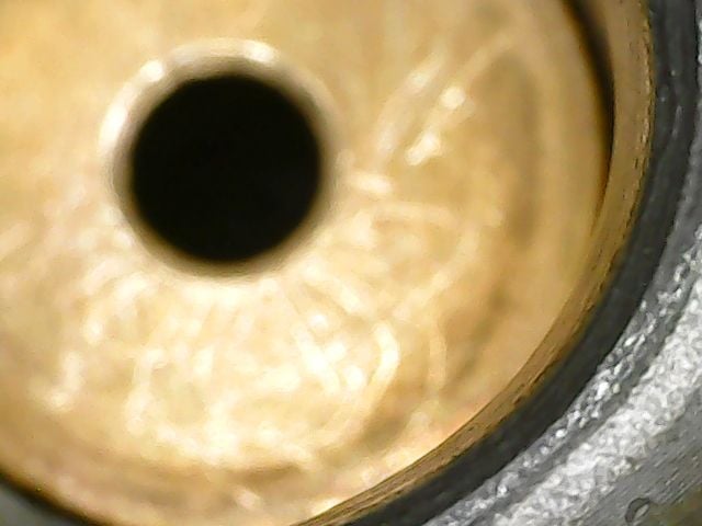
at that I should have left it alone and put the engine together.. but no no no I can not LOL leave things alone, no, not me, can't do it. when using my digital microscope I fond a scratch in the new seat and of course I had to clean it up with more seating, and when I did, where the seat was very thin, the valve seat opened into the port, because as I said^ the Valve Stem was not parallel with the Port walls.. never the less I have proven you can make new seats with a larger valve, if having to do so.
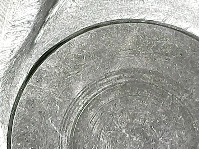
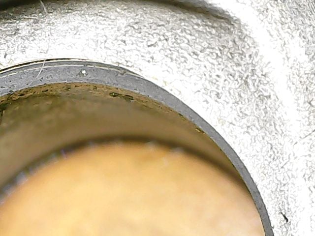
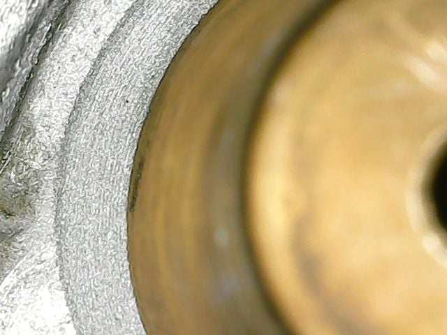
below you can see the larger 100 valve installed and were it opened to the port, in the other pic you can see an older Pic where the seat was vary thin. in another pic you can see the micro grooves in the new seat's widest point. in the other pick you can see the black compound after seating/before cleaning. I tried to get a Pic of both valves installed but I could not do it with the digital microscope.
Jim
what I found was 2 problems in my 91's cylinder. one is that the intake's Valve Stem was not parallel with the Port walls. and the 2nd is that the Face of the 91 Valve was not so level with the celling of the chamber. so that means the face of the 100 valve would not be level ether to the celling of the chamber.
but what I did find is that, the old saying is true. there is more than one way to put a shoe on LOL. I was able to cut a new valve seat with the larger 100 valve with Seating Compound. I figured I could because the valve is much harder than the aluminum cylinder. I also learned, that you can make microscopic grooves in the aluminum when seating by using too much seating compound, thanks to Lonnie I learned it's a form of hydraulician.
I started the new seat with 120 grit seating compound, then when I was close to were the face of the valve should be I used 250 grit compound. because of all the cleaning I did to keep the stem clean of compound all that only took about 1.5 hours. in the new seat I found a very small differences between the 120 and 250 grits. then I took a 2nd new 100 valve and I used 400 grit compound, here too I found little difference in the seat with the 400 grit. never the less when finished the valve did seal, I tested this by cleaning up, mounted the Intake Manifold/with Oring, adding a short, thick rubber tube over the manifold and held the valve shut with my finger as I blew very-very hard into the intake.
at that I should have left it alone and put the engine together.. but no no no I can not LOL leave things alone, no, not me, can't do it. when using my digital microscope I fond a scratch in the new seat and of course I had to clean it up with more seating, and when I did, where the seat was very thin, the valve seat opened into the port, because as I said^ the Valve Stem was not parallel with the Port walls.. never the less I have proven you can make new seats with a larger valve, if having to do so.
below you can see the larger 100 valve installed and were it opened to the port, in the other pic you can see an older Pic where the seat was vary thin. in another pic you can see the micro grooves in the new seat's widest point. in the other pick you can see the black compound after seating/before cleaning. I tried to get a Pic of both valves installed but I could not do it with the digital microscope.
Jim