


JW Büker Jungmeister build
 06-22-2022, 01:38 AM
#76

Before I go on, I did discover one thing that I want to emphasize now before I forget. While bolting on the bottom wing center section for the first time I found out that I should've installed the blind nuts on the rear mount parts. The rear ones are "blind" so I had to go through major contortions to get the blind nuts in. I'll highlight this now:
!!!!!!!!!INSTALL BLIND NUTS FOR BOTTOM WING CENTER SECTION PRIOR TO ASSEMBLY!!!!!!!!!!!
!!!!!!!!!INSTALL BLIND NUTS FOR BOTTOM WING CENTER SECTION PRIOR TO ASSEMBLY!!!!!!!!!!!

The following users liked this post:
tmac48 (11-01-2022)
06-22-2022, 02:00 AM
#77
So the plans pretty much peter out at this point. So we're on our own now floks!!
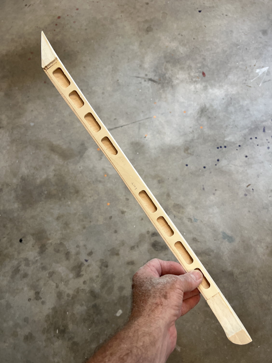
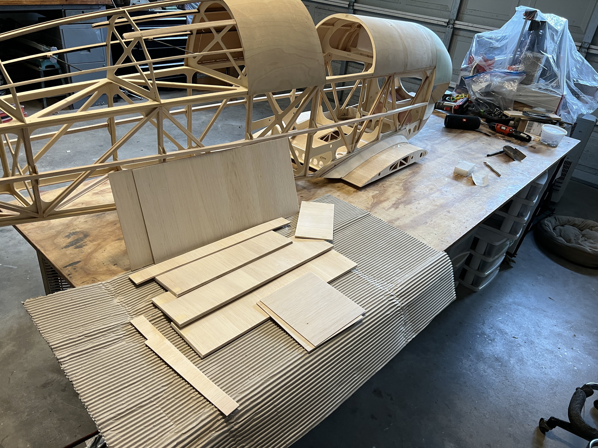
With the front end done I decided to install the big side stringers. And here's where it gets interesting: the instructions (such as they are) call for installing 10x18mm balsa. However, the kit doesn't have any 10x18 specifically. There is a large 10x50 board left over though. It's about 30 inches long and I couldn't see any other use for it so I split into 3 lengths for this purpose. However: this is not going to be enough for full length/width both side. But we don't need full width all the way back. Toward the rear it's going to taper down to less than 10mm so here's what I did (like I said, we're on our own). .. . . .SO:
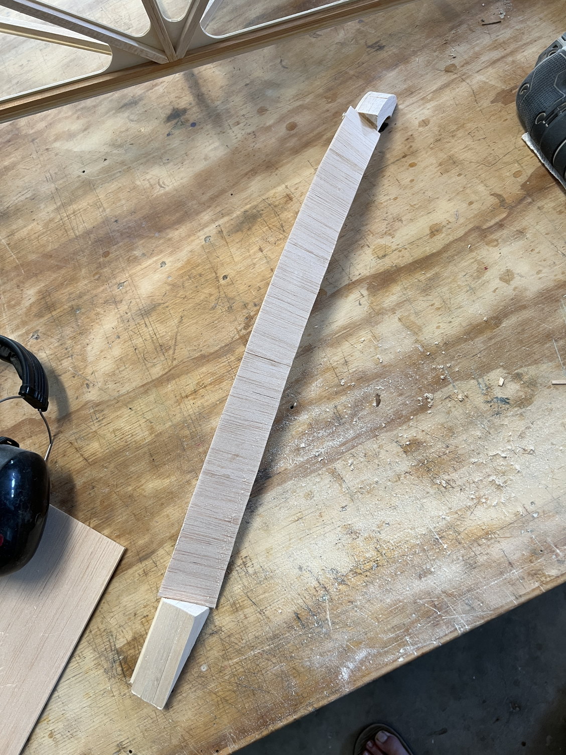
I split the board into 3 pieces. I cut one piece in half and scarf joined each piece onto the two left over pieces. I then scarfed a 10x10mm stick onto each one of those. I now had two LONG tapering side stringers that are perfect for the purpose.
I'm very happy right now. . . . . . until I find out we needed that board for something else!!!!!
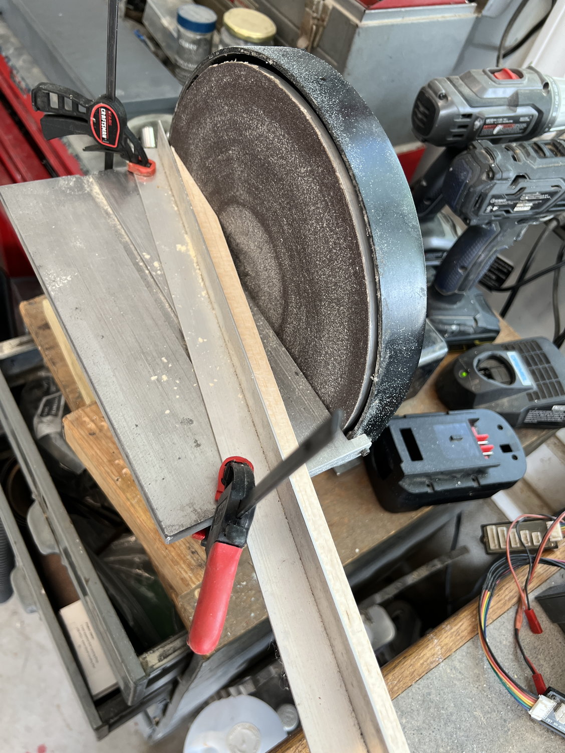
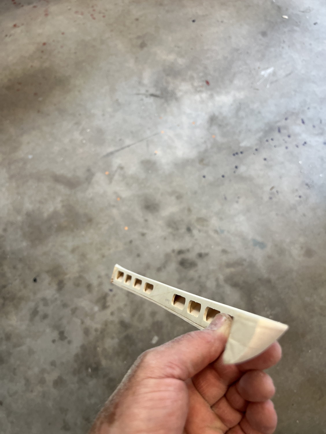
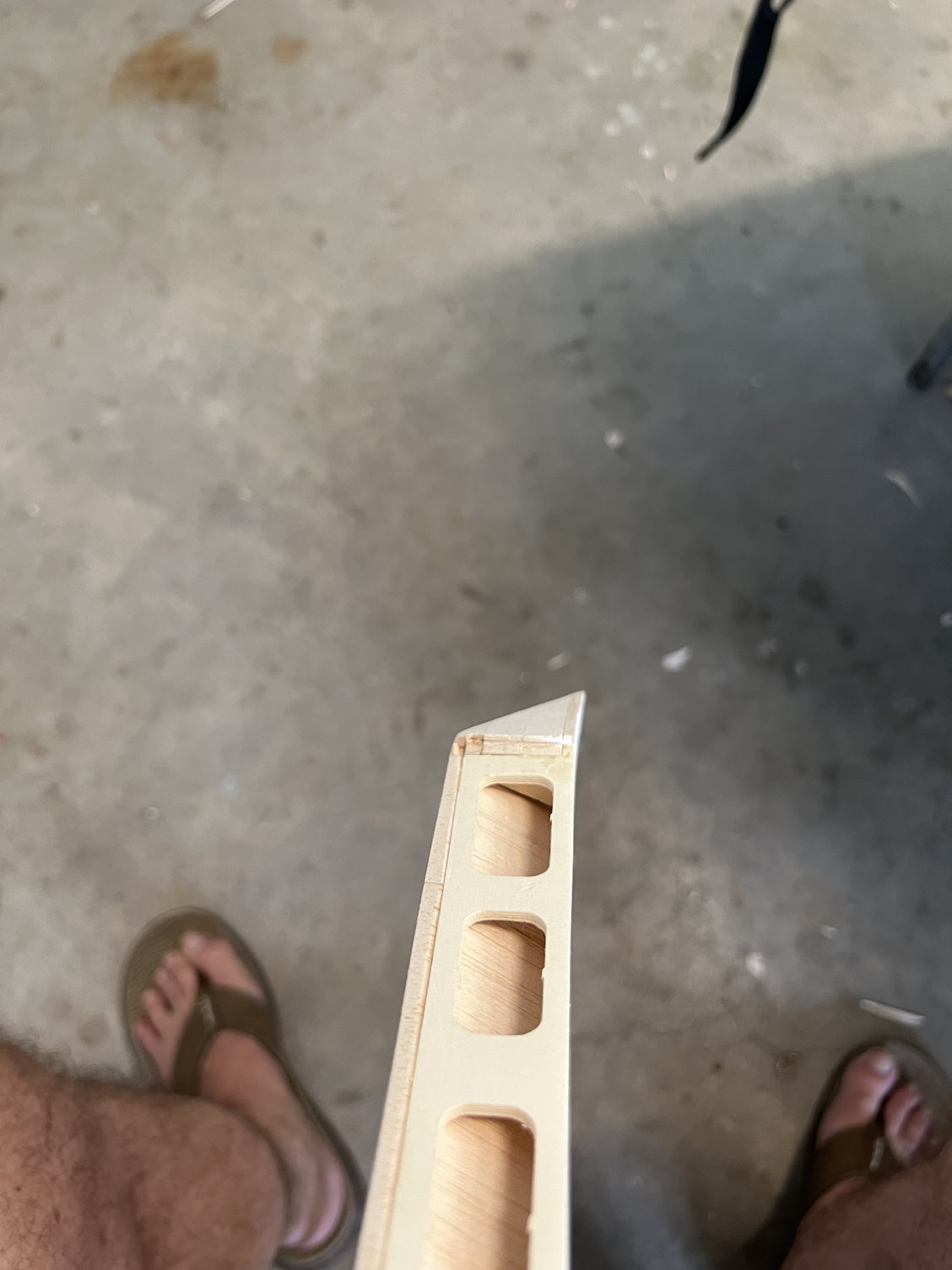
This is how I do my scarf joints. I'm using this angle (approx 12:1) because the JW uses this ratio on other pieces provided. It also happens to be aircraft industry standard.
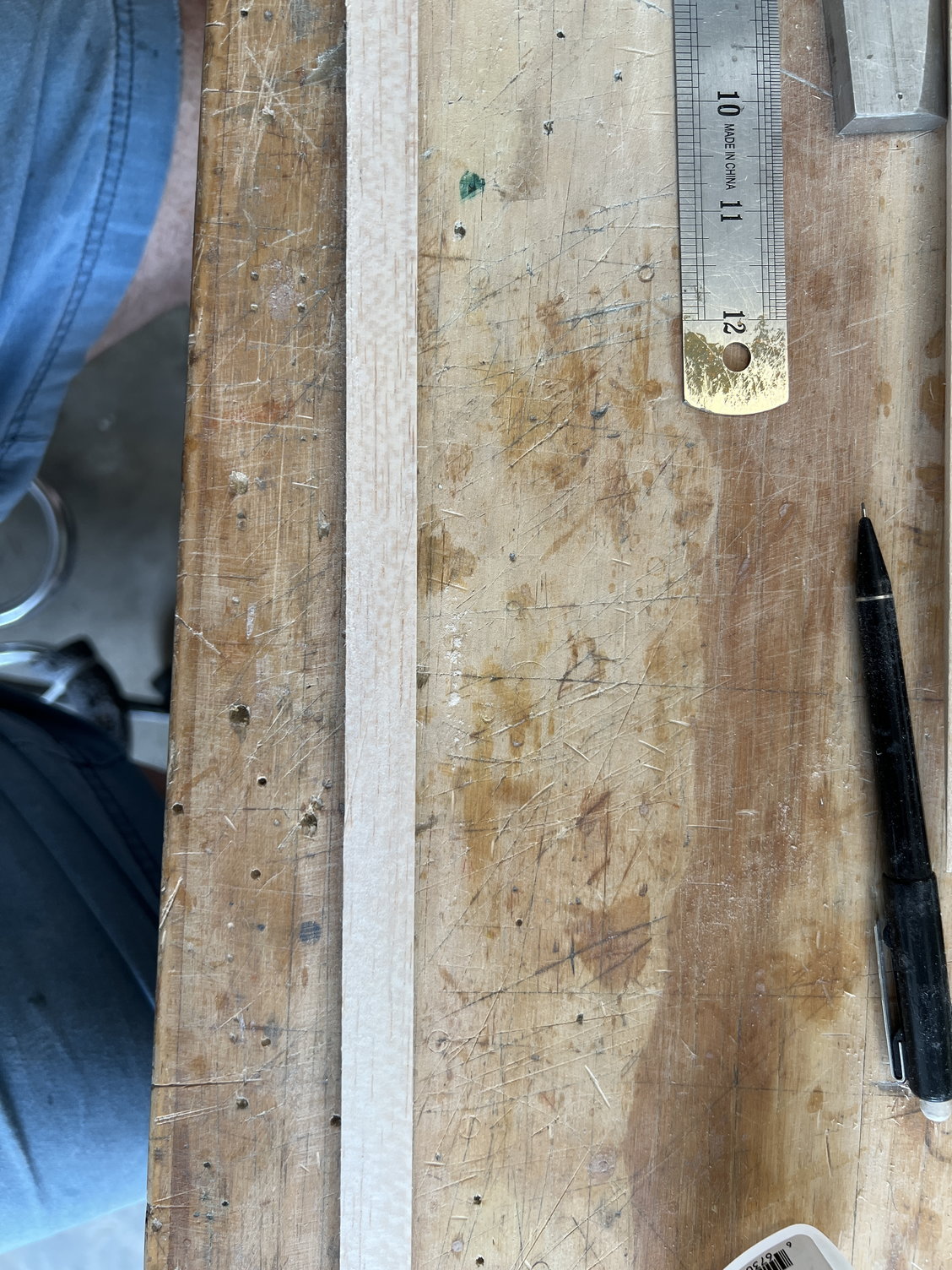
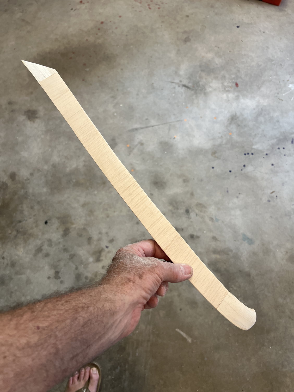
Can you see the scarf?
Here are the two finished tapered stringers
With the front end done I decided to install the big side stringers. And here's where it gets interesting: the instructions (such as they are) call for installing 10x18mm balsa. However, the kit doesn't have any 10x18 specifically. There is a large 10x50 board left over though. It's about 30 inches long and I couldn't see any other use for it so I split into 3 lengths for this purpose. However: this is not going to be enough for full length/width both side. But we don't need full width all the way back. Toward the rear it's going to taper down to less than 10mm so here's what I did (like I said, we're on our own). .. . . .SO:
I split the board into 3 pieces. I cut one piece in half and scarf joined each piece onto the two left over pieces. I then scarfed a 10x10mm stick onto each one of those. I now had two LONG tapering side stringers that are perfect for the purpose.
I'm very happy right now. . . . . . until I find out we needed that board for something else!!!!!
This is how I do my scarf joints. I'm using this angle (approx 12:1) because the JW uses this ratio on other pieces provided. It also happens to be aircraft industry standard.
Can you see the scarf?
Here are the two finished tapered stringers
The following users liked this post:
Steve (06-22-2022)
The following users liked this post:
Steve (06-22-2022)
06-22-2022, 10:40 AM
#79
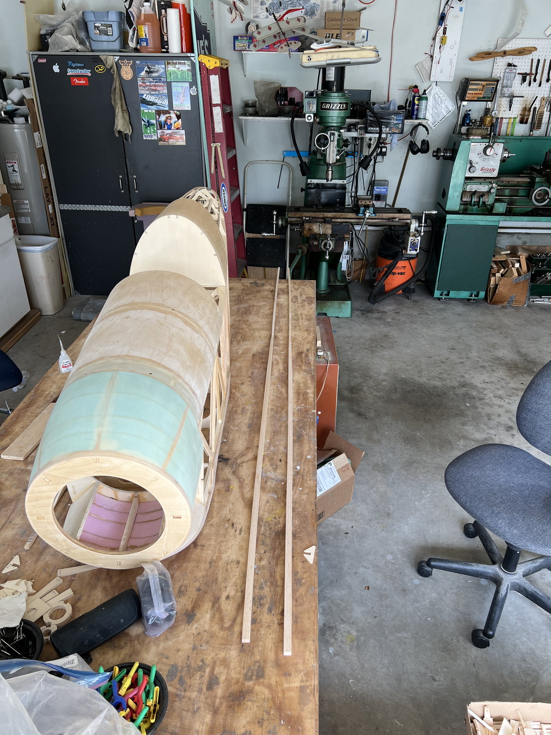
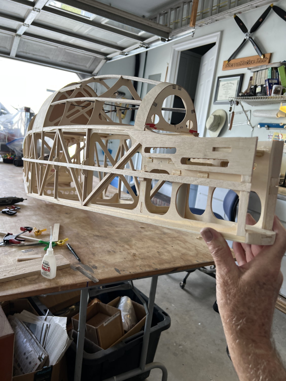
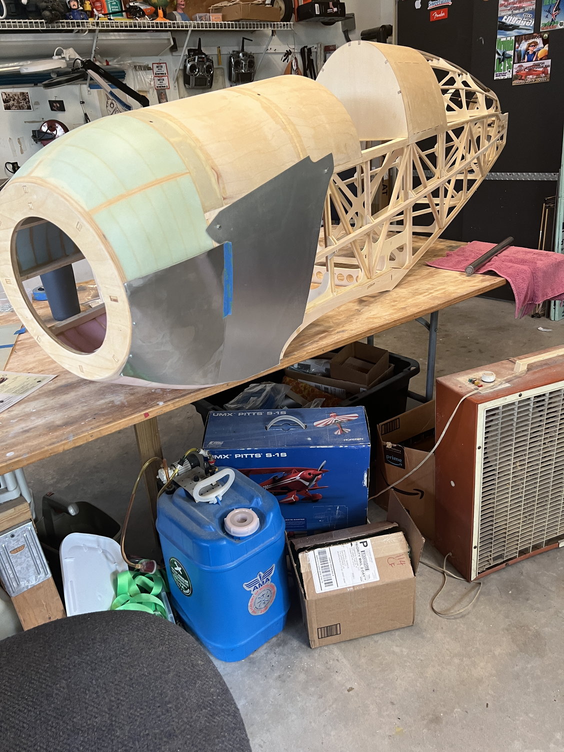
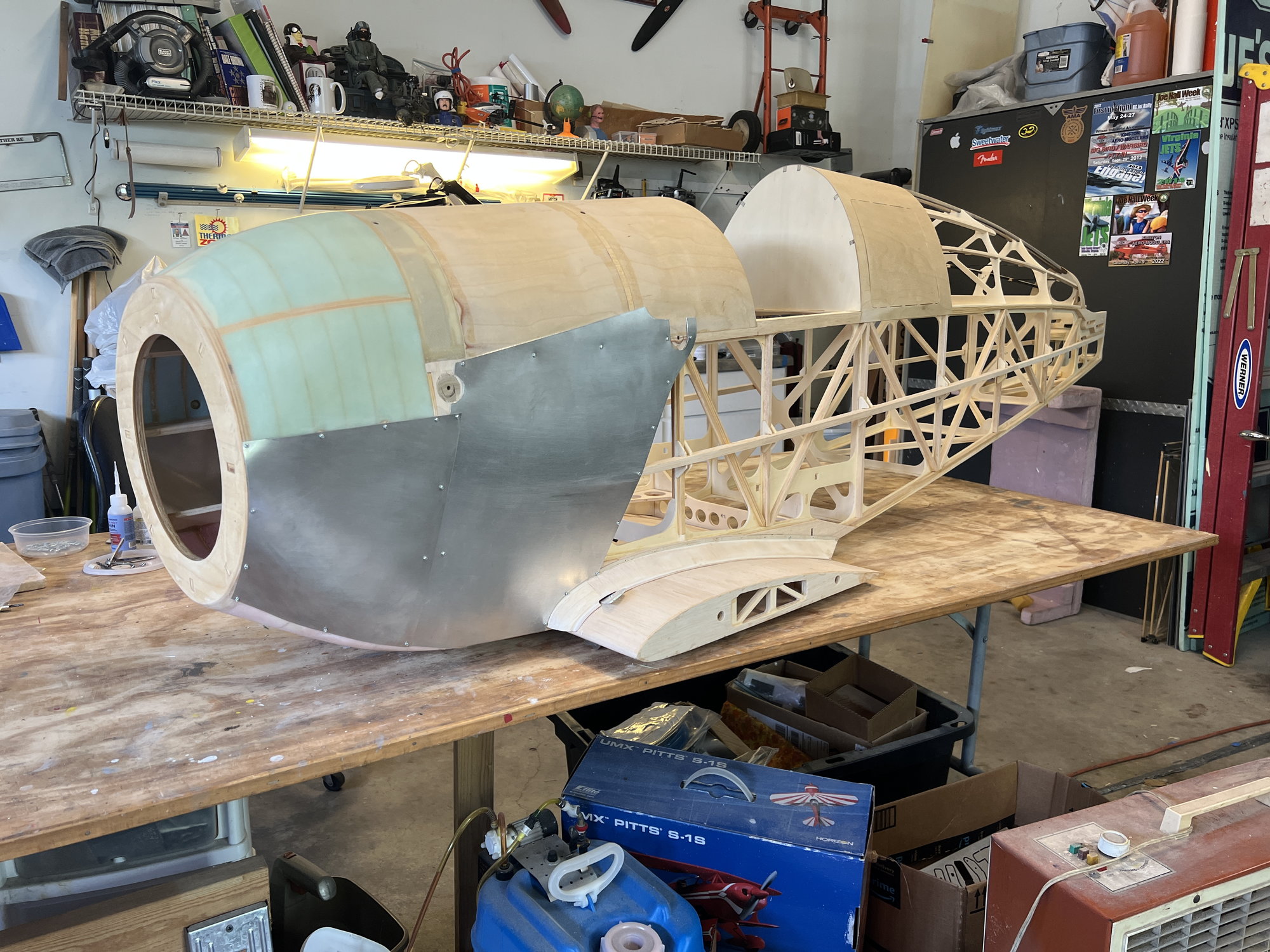
Okay, I finally arrived at the place where I needed to deal with the aluminum plates that JW decided to use on the forward fuselage. I didn't really like the look of them from afar and now that I'm looking at it right on my bench I'm really disappointed. Let me say up front, I NEVER intended to use the metal plates as provided. I just hate the way they look when bent up to fit over the struts. (I guess if you were a real expert metal worker you might get results that were presentable??) But I did plan to use the plates in some, non bent-up, state. I guess it was JW's attempt to recreate a version of the full scale Bucker that has the bent up (albeit tastefully) covers. But JW abandoned true scale fidelity in this kit a long time before this! Cancelling this idea would've been a more worthy concession than most.
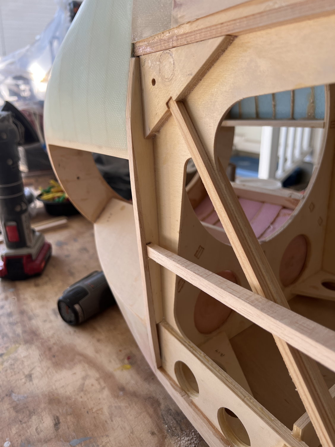
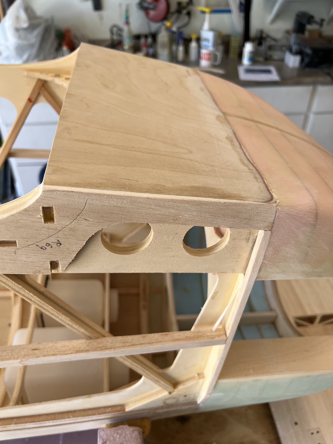
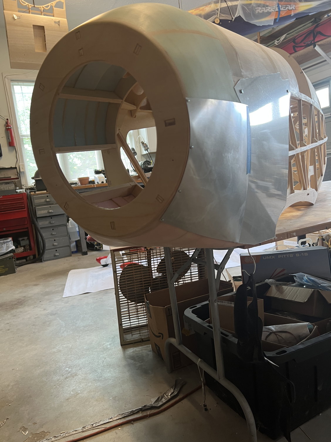
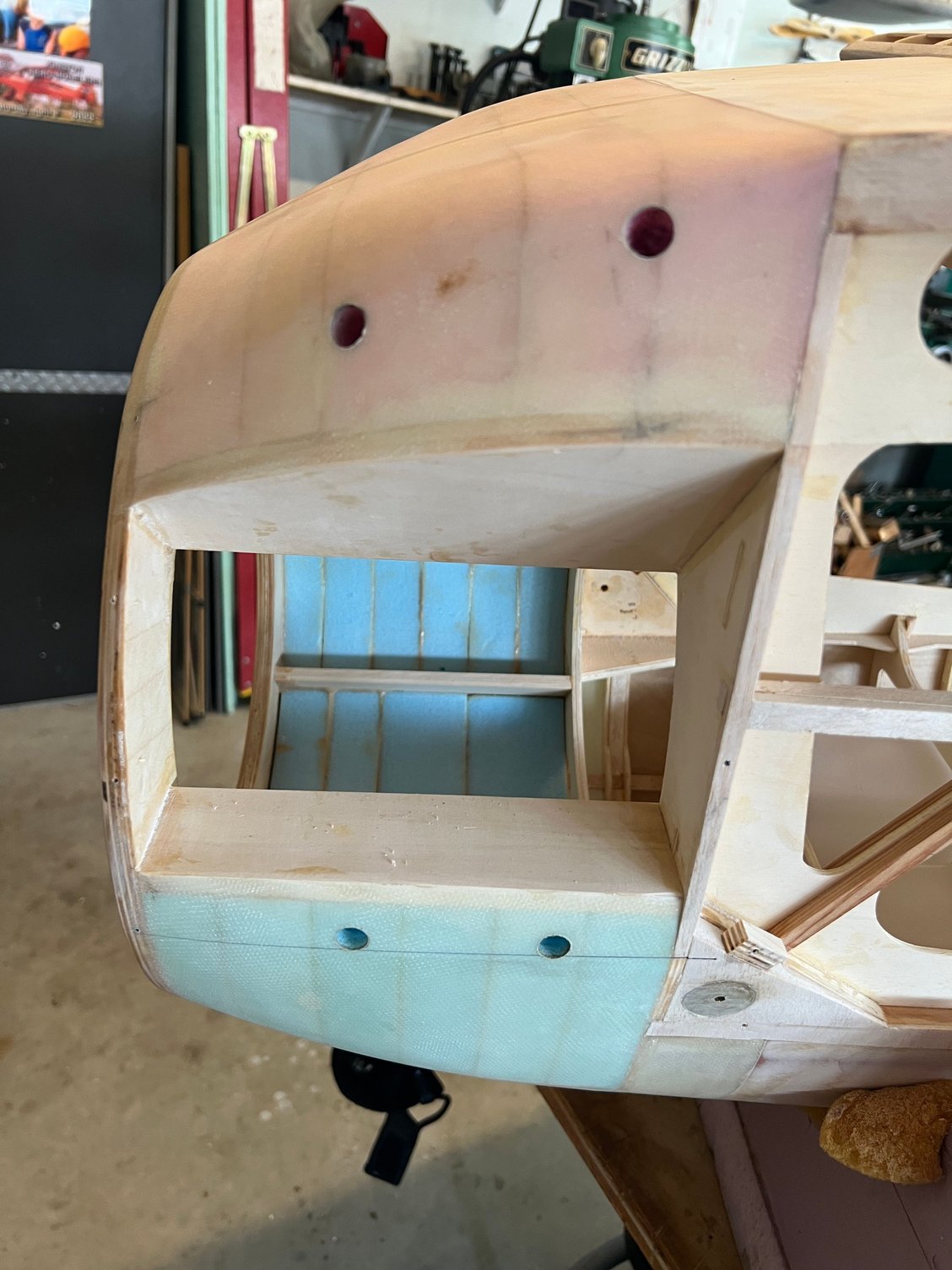
Anyway, that's not the big headline here. The design of the fuselage UNDER all that metal is the real problem. It is very hard to describe but the bottom line is that the planes of the fuselage that need to come together in the front of the fuselage DON'T! I honestly have zero idea what JW intended. So I've gone back and looked at all the completed JW Buckers I can find and sure enough, the metal work never seems to fit quite right. A picture is worth a thousand words so here are the pictures:
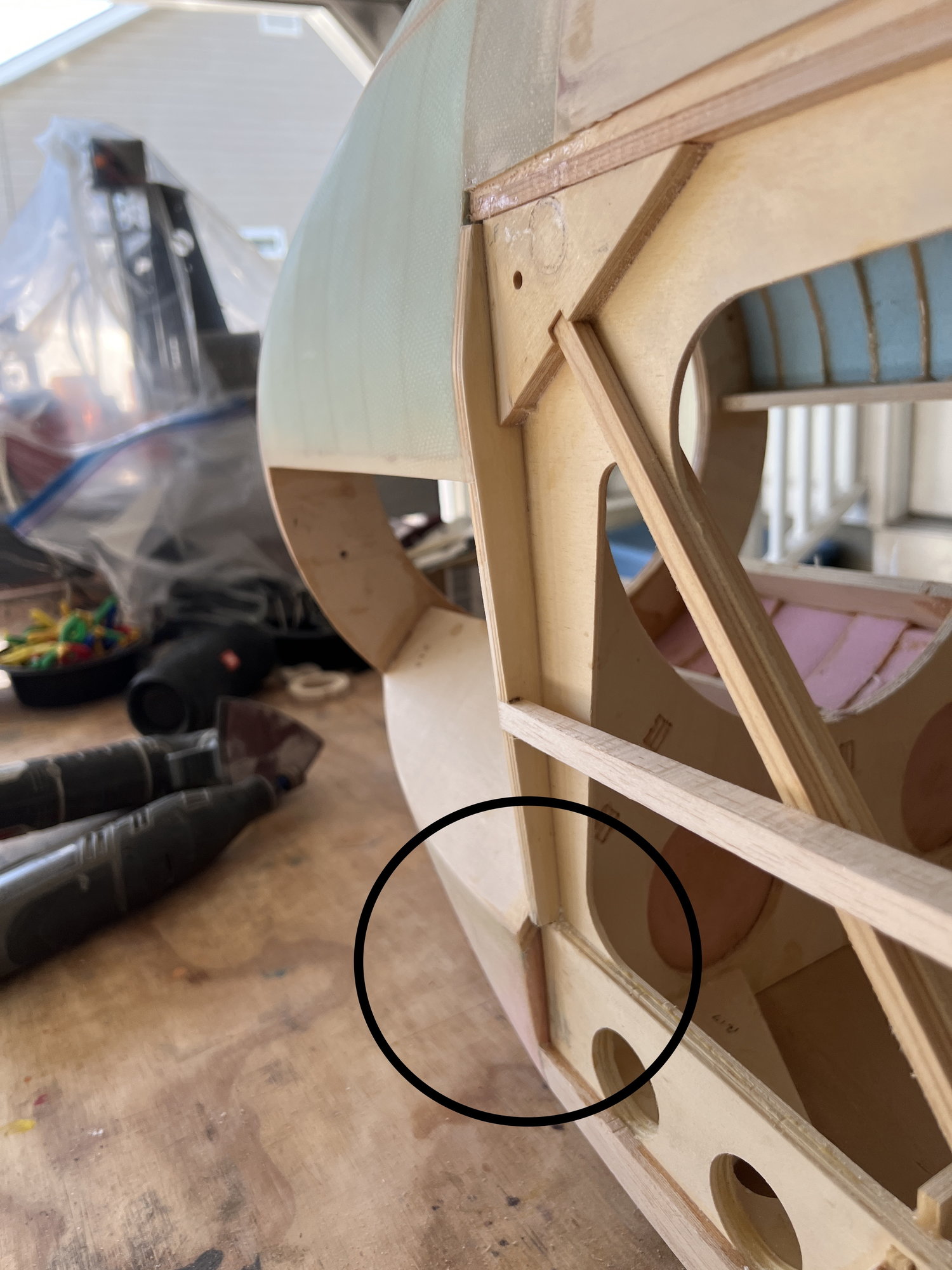
Here is the culprit. The fuselage bulkhead angles in and leaves a (perplexing!) miss alignment with the rest of the front end. Sorry, but I just don't get it.
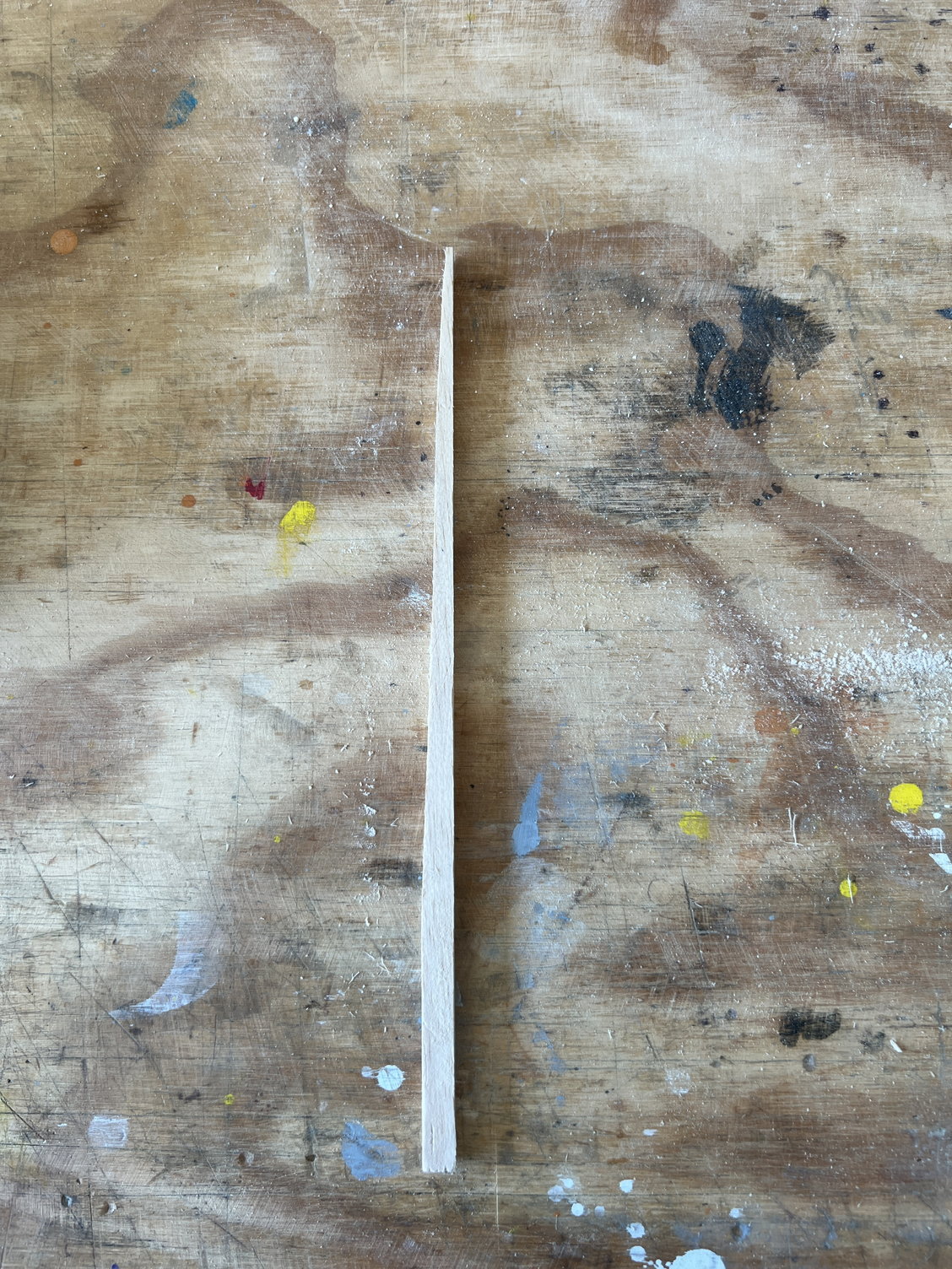
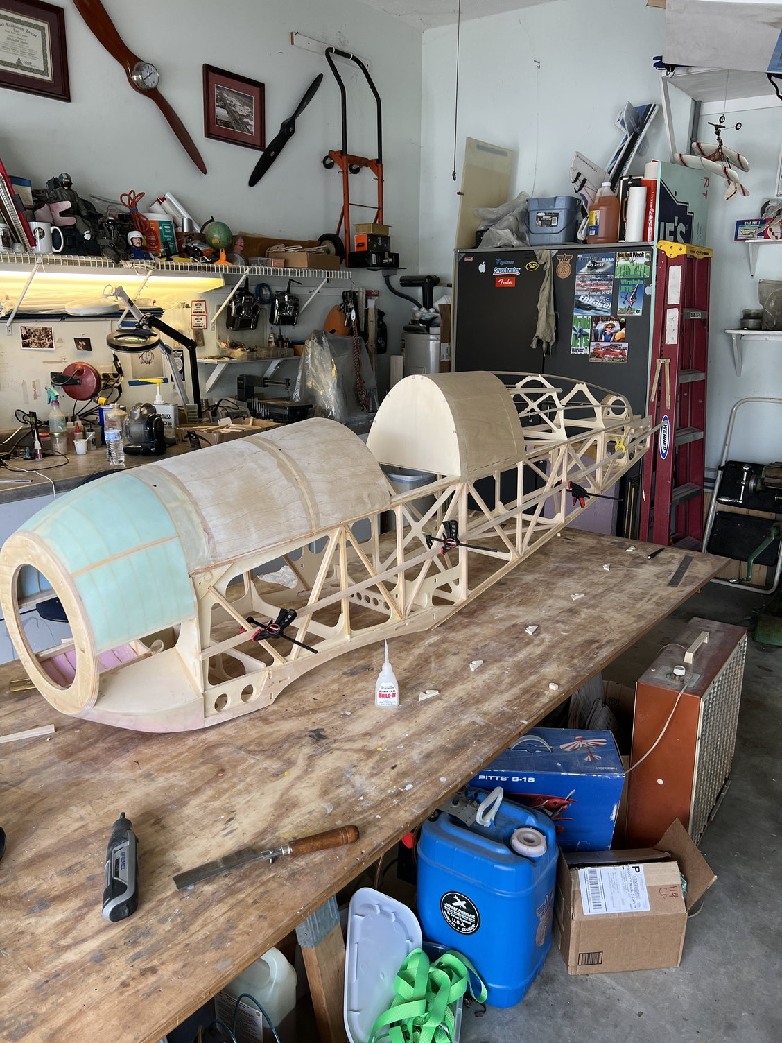
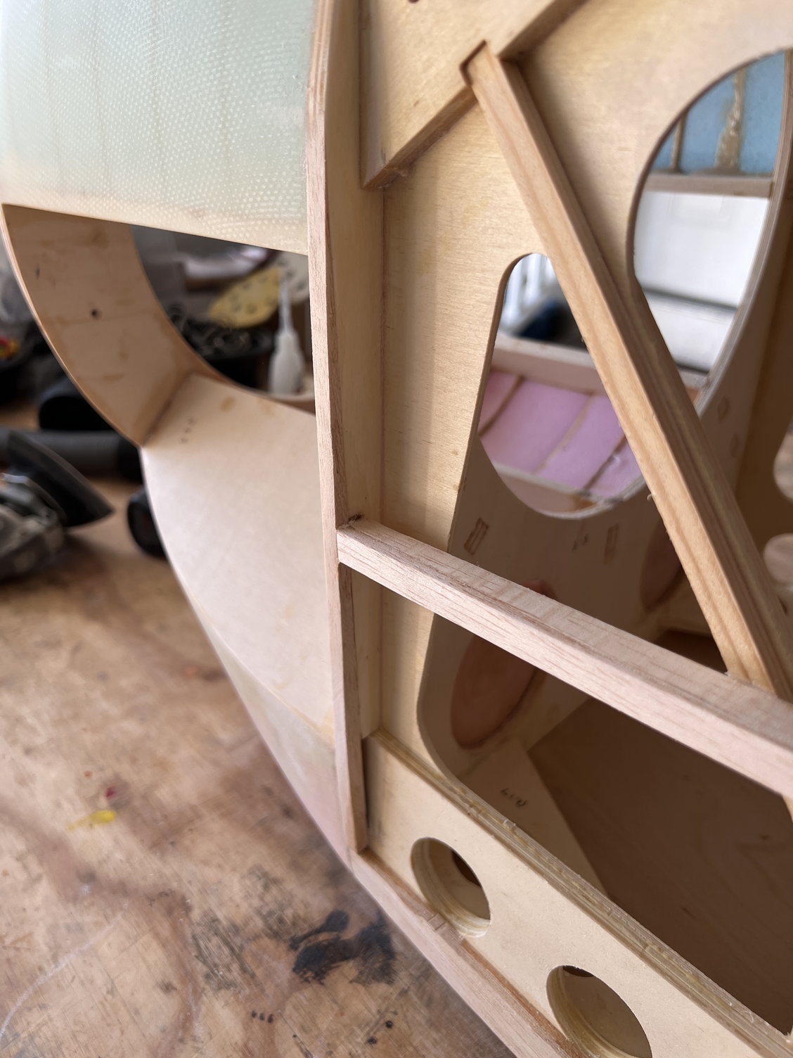
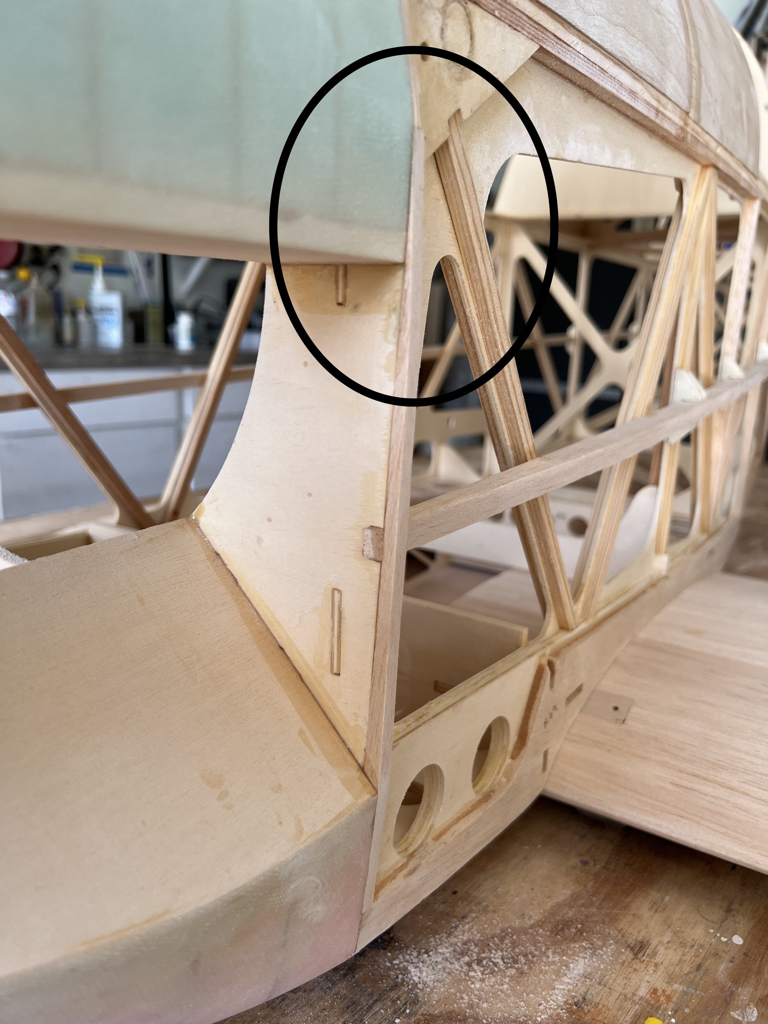
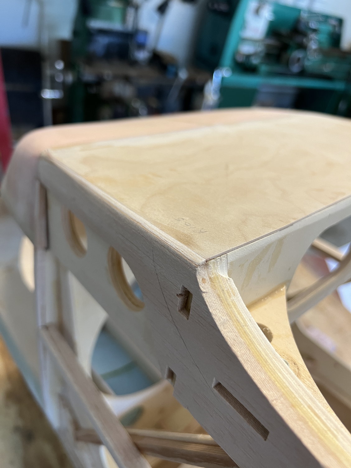
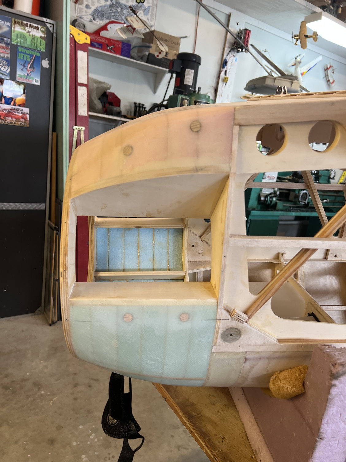
Here's the fix
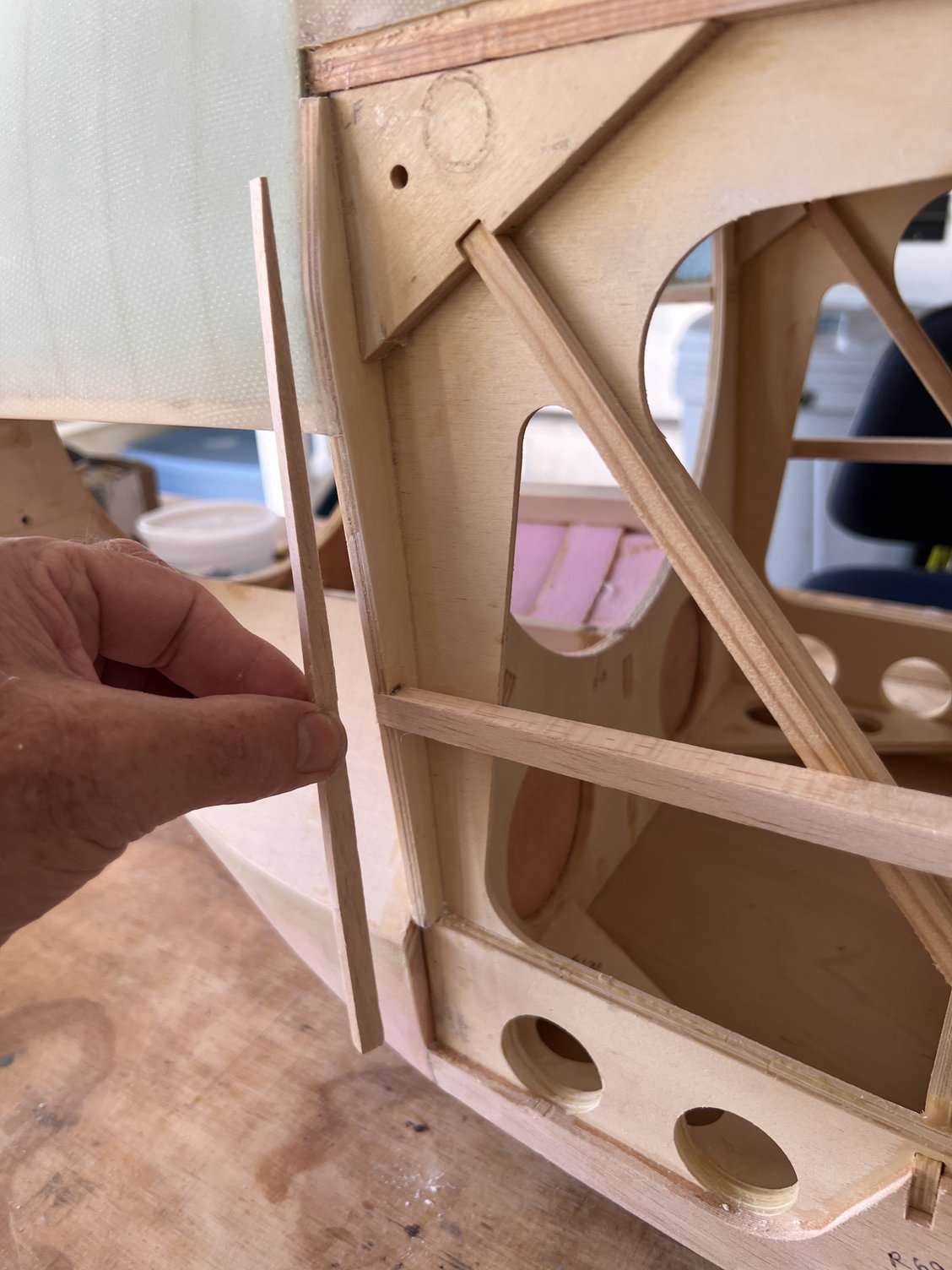
Wish I had figured this out before I tapered the side stringer into the front former. I just had to make up a long wedge to replace what I originally removed.
Here's the fix before I replace the (now) missing side stringer material.
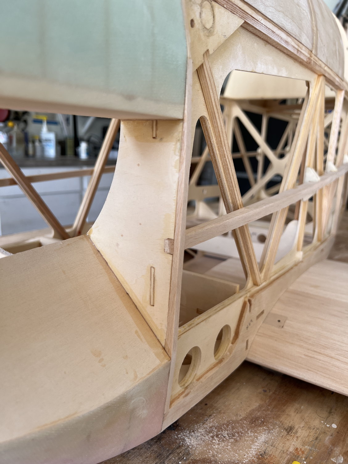
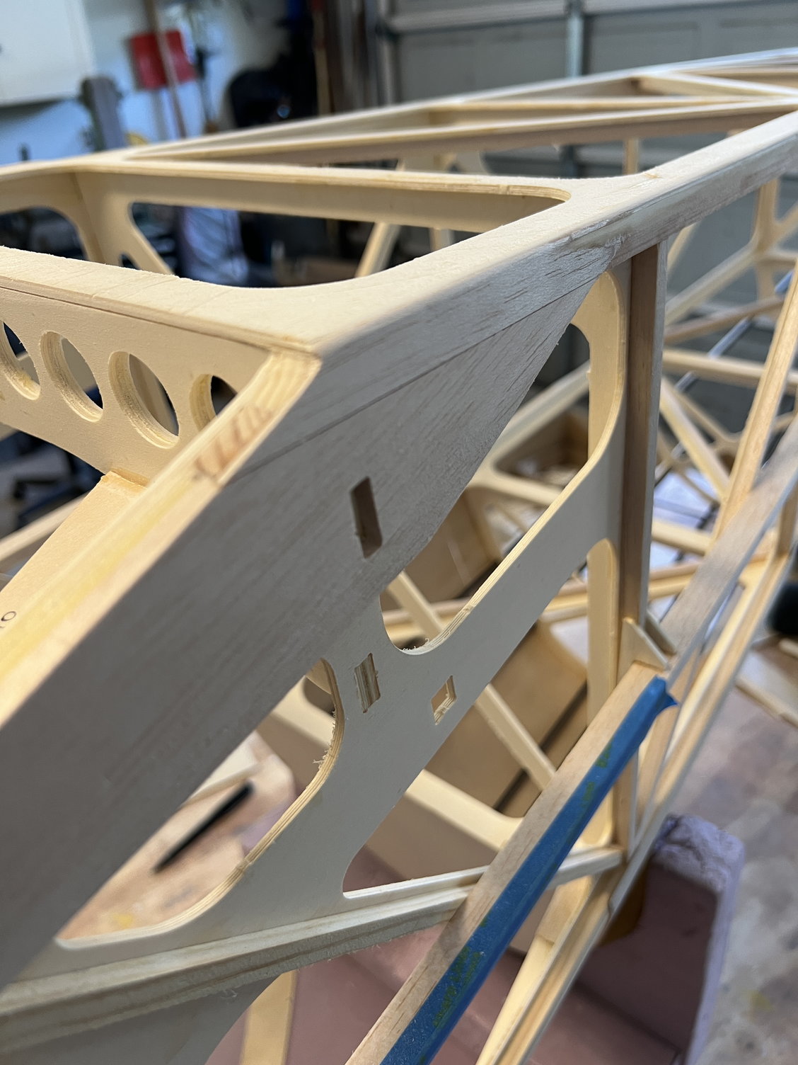
Viola! All the planes come together for covering/metal panels.
Ready to cover.
As I said, I will be using the plates in an altered manner. They allow internal access to the front fuselage that I would miss if I didn't use them.
Anyway, that's not the big headline here. The design of the fuselage UNDER all that metal is the real problem. It is very hard to describe but the bottom line is that the planes of the fuselage that need to come together in the front of the fuselage DON'T! I honestly have zero idea what JW intended. So I've gone back and looked at all the completed JW Buckers I can find and sure enough, the metal work never seems to fit quite right. A picture is worth a thousand words so here are the pictures:
Here is the culprit. The fuselage bulkhead angles in and leaves a (perplexing!) miss alignment with the rest of the front end. Sorry, but I just don't get it.
Here's the fix
Wish I had figured this out before I tapered the side stringer into the front former. I just had to make up a long wedge to replace what I originally removed.
Here's the fix before I replace the (now) missing side stringer material.
Viola! All the planes come together for covering/metal panels.
Ready to cover.
As I said, I will be using the plates in an altered manner. They allow internal access to the front fuselage that I would miss if I didn't use them.
Last edited by mitchilito; 06-22-2022 at 10:44 AM.
06-25-2022, 03:10 AM
#80
Let me say that if I was building this kit again I would do the above fix PRIOR to shaping and glassing the top foam blocks. . . .
As it is I now have a little miss match at the top but I'm thinking the front metal plate will span it so it's not noticeable.
As it is I now have a little miss match at the top but I'm thinking the front metal plate will span it so it's not noticeable.
Last edited by mitchilito; 06-25-2022 at 03:17 AM.
The following users liked this post:
Steve (07-01-2022)
06-25-2022, 11:17 AM
#81
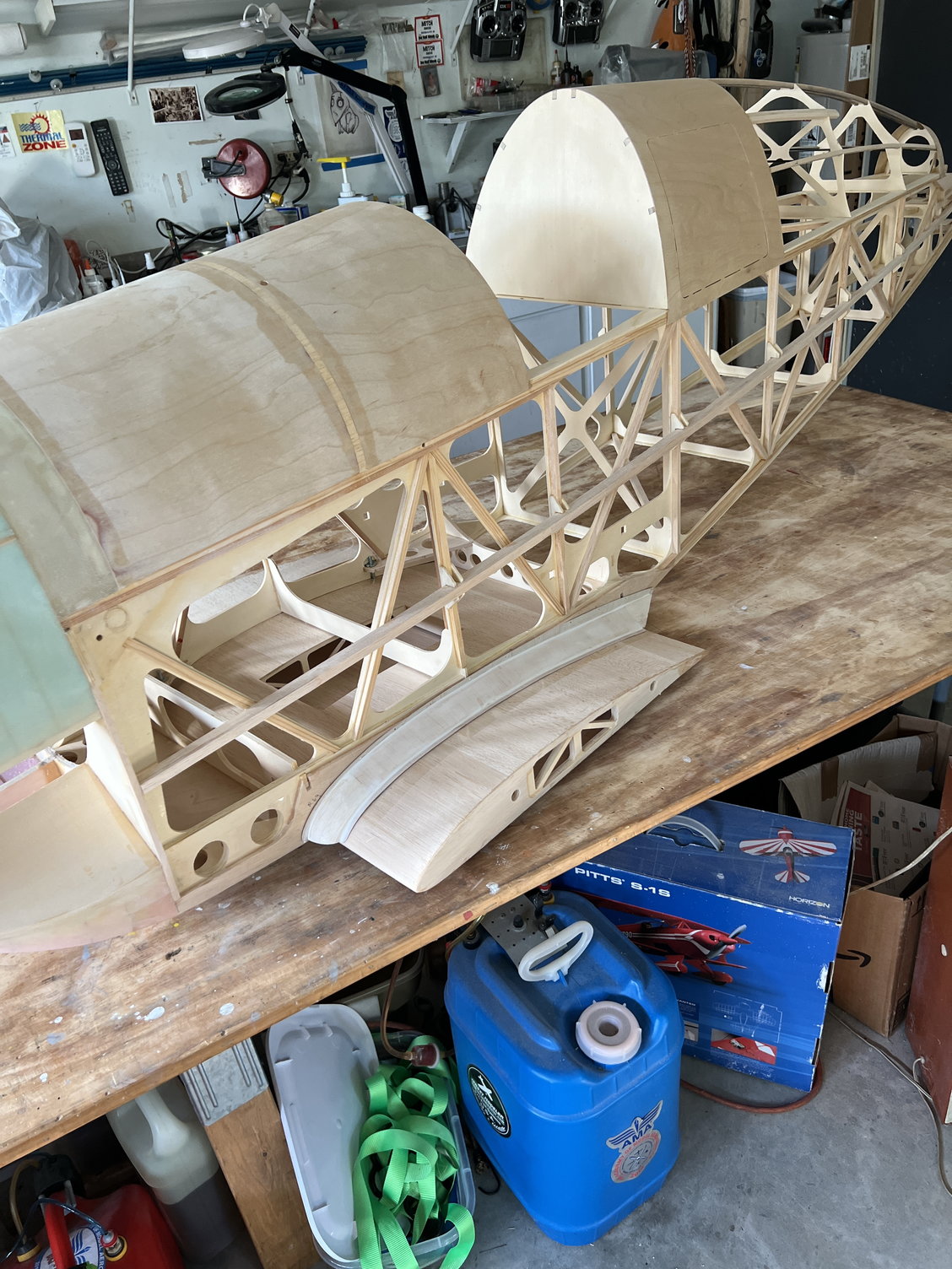
So for whatever reason, I picked this time to work on the wing farings and it's an interesting process to be sure. I'm going to caption pictures to document the process:
First thing I did was put fill one the bottom front and back. Here's the front fill
Sanded
Here's the back fill.
Here I'm checking for the fall of the covering.
Here I'm sanding the whole aft area to account for the covering fall prior to installing the fairings.
First thing I did was put fill one the bottom front and back. Here's the front fill
Sanded
Here's the back fill.
Here I'm checking for the fall of the covering.
Here I'm sanding the whole aft area to account for the covering fall prior to installing the fairings.
06-25-2022, 11:31 AM
#82
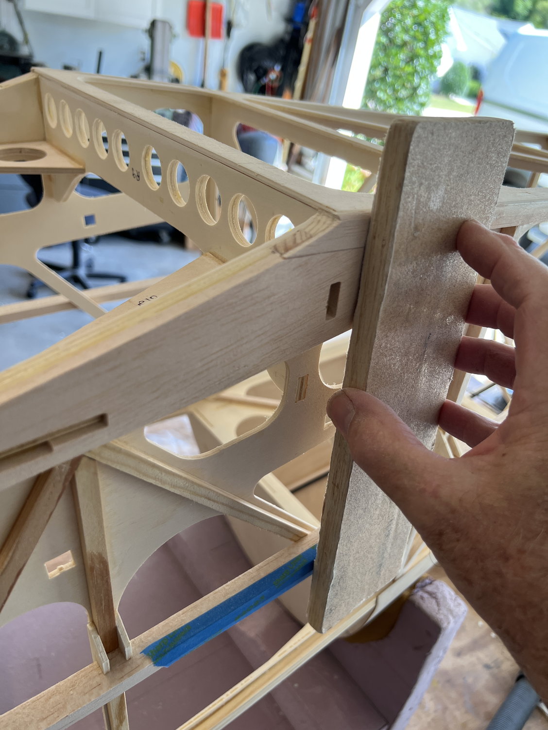
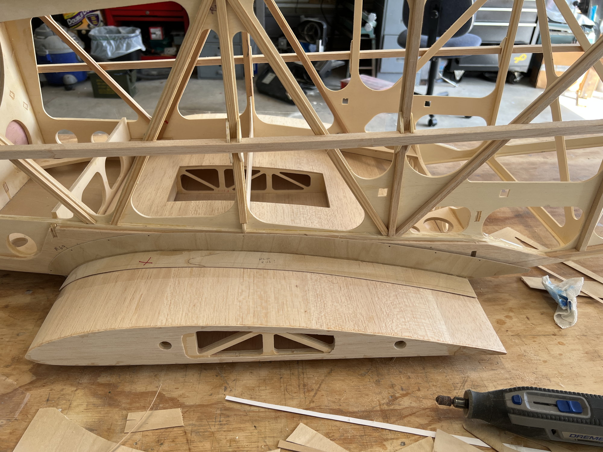
I can tell you in advance that the fairings are NOT simply flat straight lines against the fuselage. On the contrary, you'll see that they bend a LOT towards the back end. Pics:
The first thing to do is sand R109 to fit the side of the fuselage. It may take quite a bit. Then tack 108 to it. You'll see I made some ply wedges to hold the angles I needed.
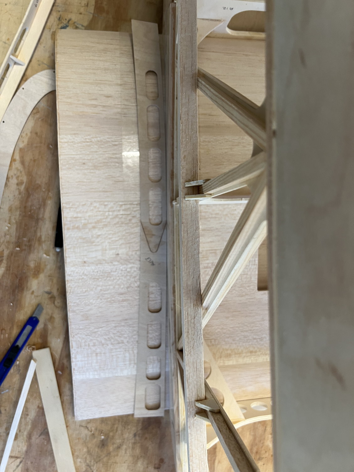
I took this pic to show how BAD R113 fits. Looks close: there is NO WAY to make them fit right. The good news is, there's plenty of scrap .8mm ply to make good ones.
I keep thinking that I must be overlooking something that would make these work. Maybe you out there in the real world can figure it out. But I doubt it. . . .
They are a very interesting design and actually turn out really nice.
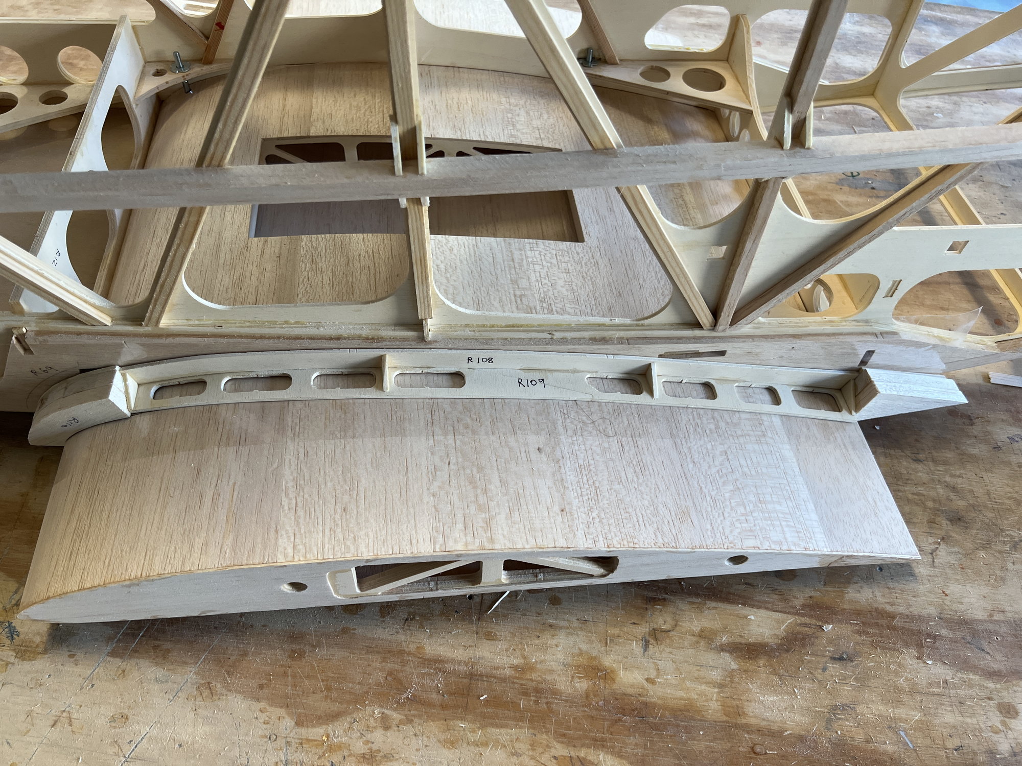
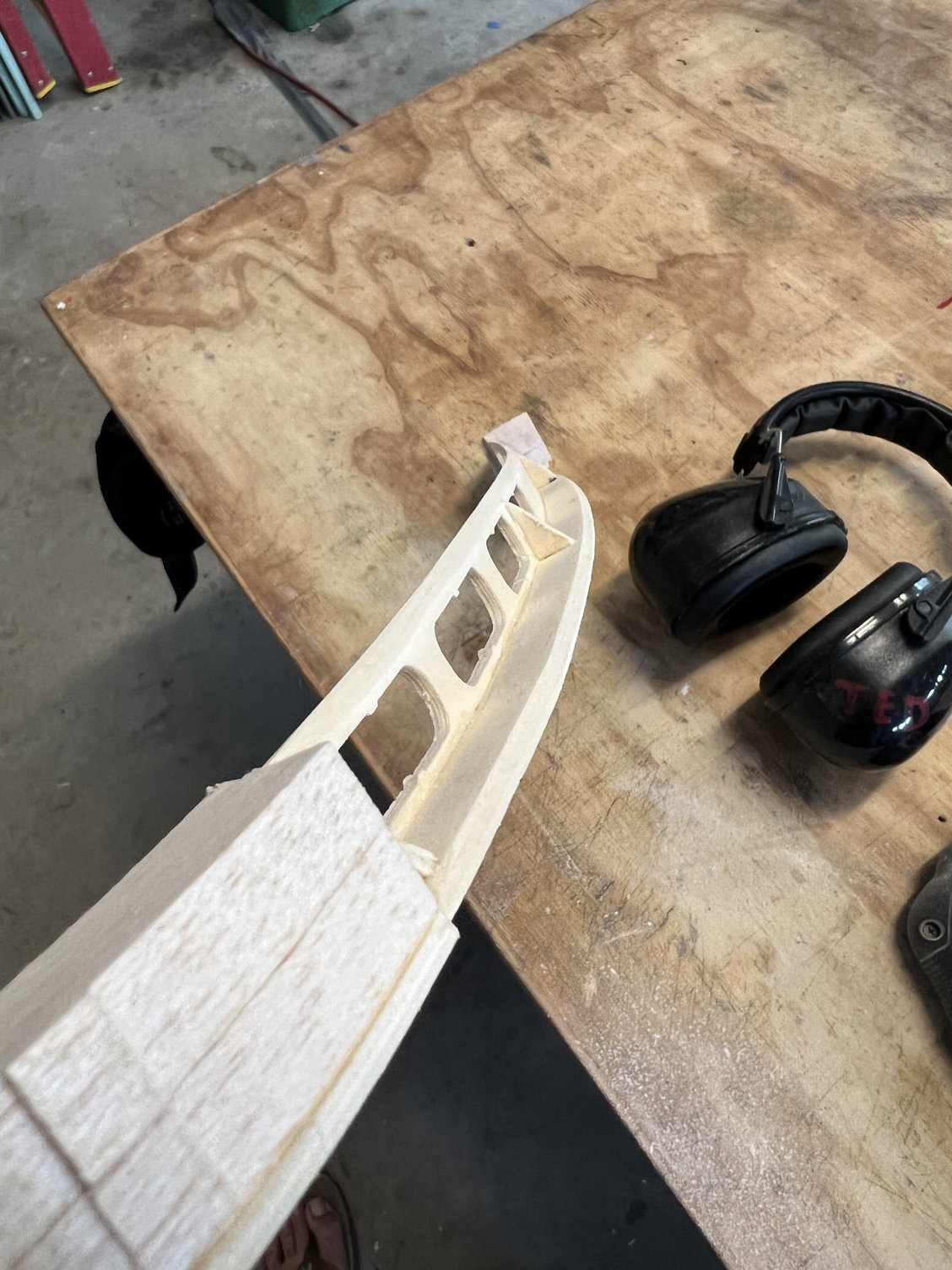
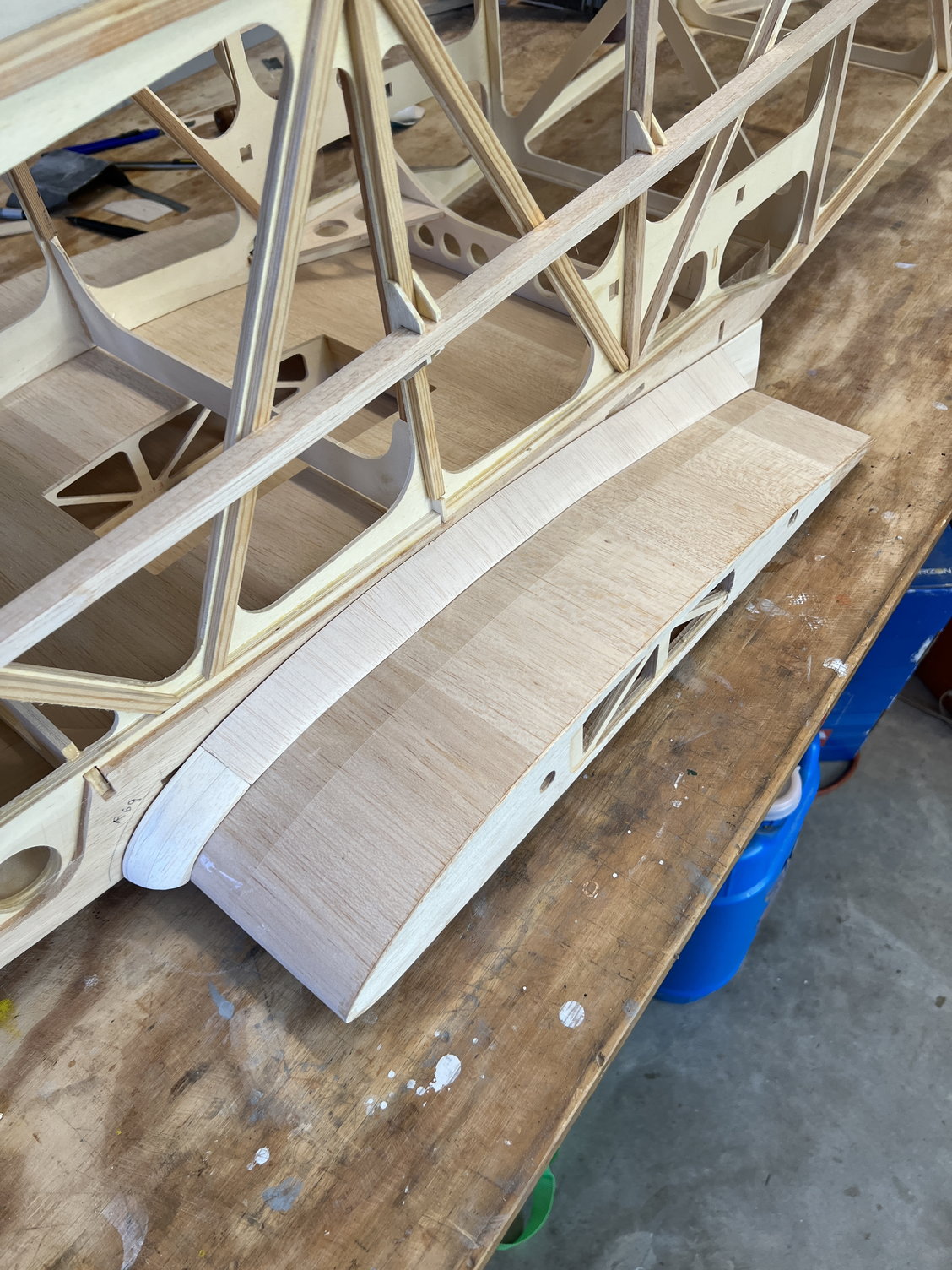
Here I'm trying to capture how they arc in toward the rear. I had to add balsa to account for some of that inside arc.
Pretty neat assemblies. I think they are going to look great. And I find it so interesting that they are actually removable.
Here's a good pic of the arc. They fit fantastically in place.
The first thing to do is sand R109 to fit the side of the fuselage. It may take quite a bit. Then tack 108 to it. You'll see I made some ply wedges to hold the angles I needed.
I took this pic to show how BAD R113 fits. Looks close: there is NO WAY to make them fit right. The good news is, there's plenty of scrap .8mm ply to make good ones.
I keep thinking that I must be overlooking something that would make these work. Maybe you out there in the real world can figure it out. But I doubt it. . . .
They are a very interesting design and actually turn out really nice.
Here I'm trying to capture how they arc in toward the rear. I had to add balsa to account for some of that inside arc.
Pretty neat assemblies. I think they are going to look great. And I find it so interesting that they are actually removable.
Here's a good pic of the arc. They fit fantastically in place.


The following users liked this post:
Steve (07-01-2022)
06-27-2022, 03:13 AM
#86
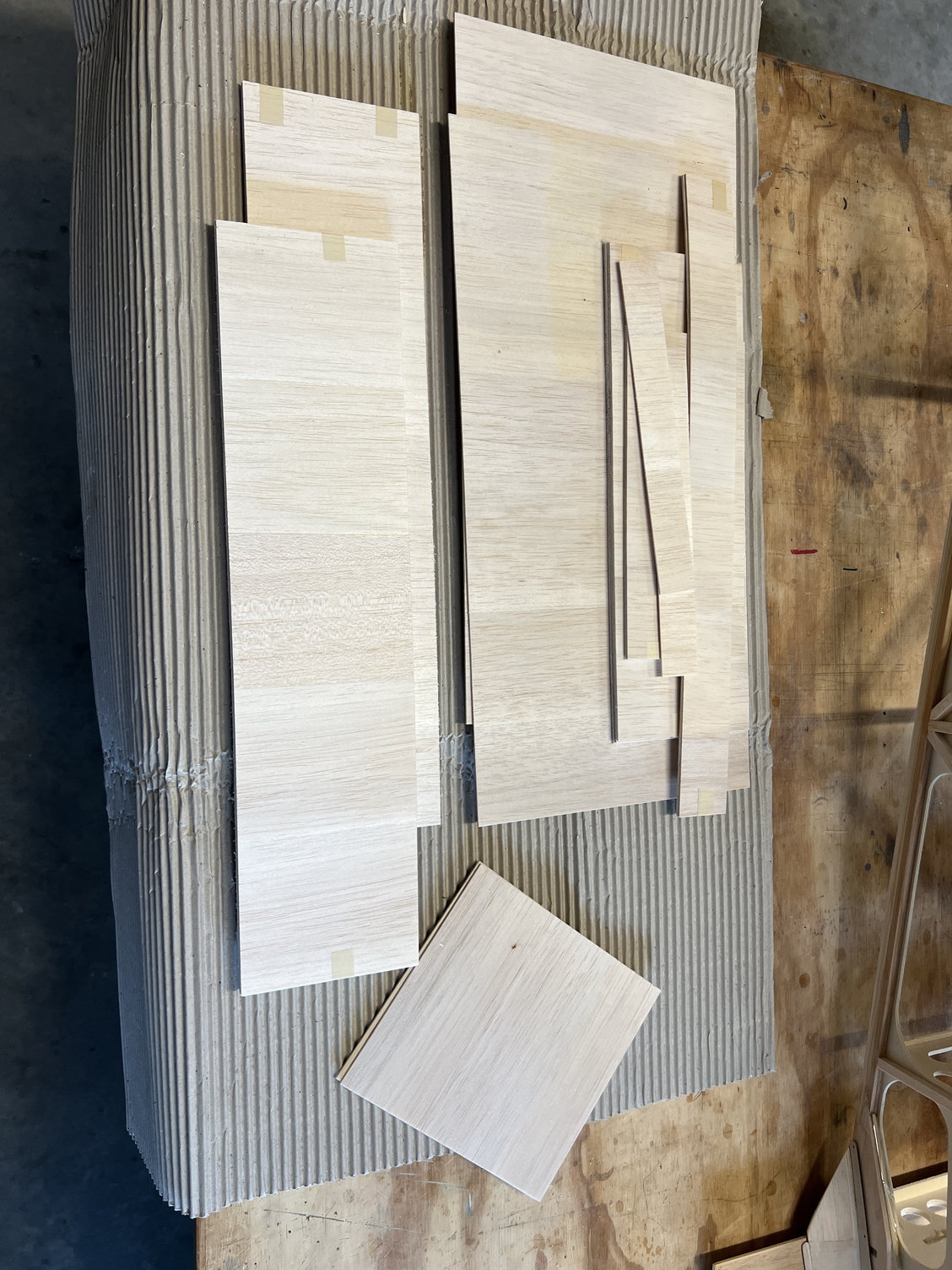
NEWS FLASH!! Those of you who have read my thread to this point have had to suffer through constant whining about lack of balsa (and other kinds of) wood provided by JW. Well yesterday I found (or should say re-found a significant bundle of balsa that has been kicking around in plain sight. I though from the beginning that it was marked "Fuselage" (I think mainly because of the small lengths) but I looked closely at it yesterday and it just says "Balsa."
If you look closely at the pics you'll see that they're short cross grain pieces and the place they would've worked would be the two wing center sections. In my defense, (for all the whining), this would not have covered all the needed material but it would've helped. So I say now officially: SORRY JW.
I'll also say again: MAN, I WISH I HAD THIS BUILD THREAD BEFORE I STARTED THIS BUILD!!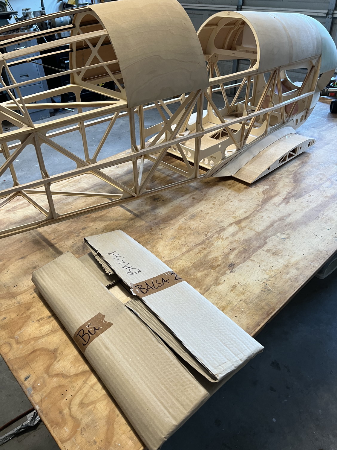
Last edited by mitchilito; 06-27-2022 at 03:18 AM.
06-27-2022, 04:11 AM
#87
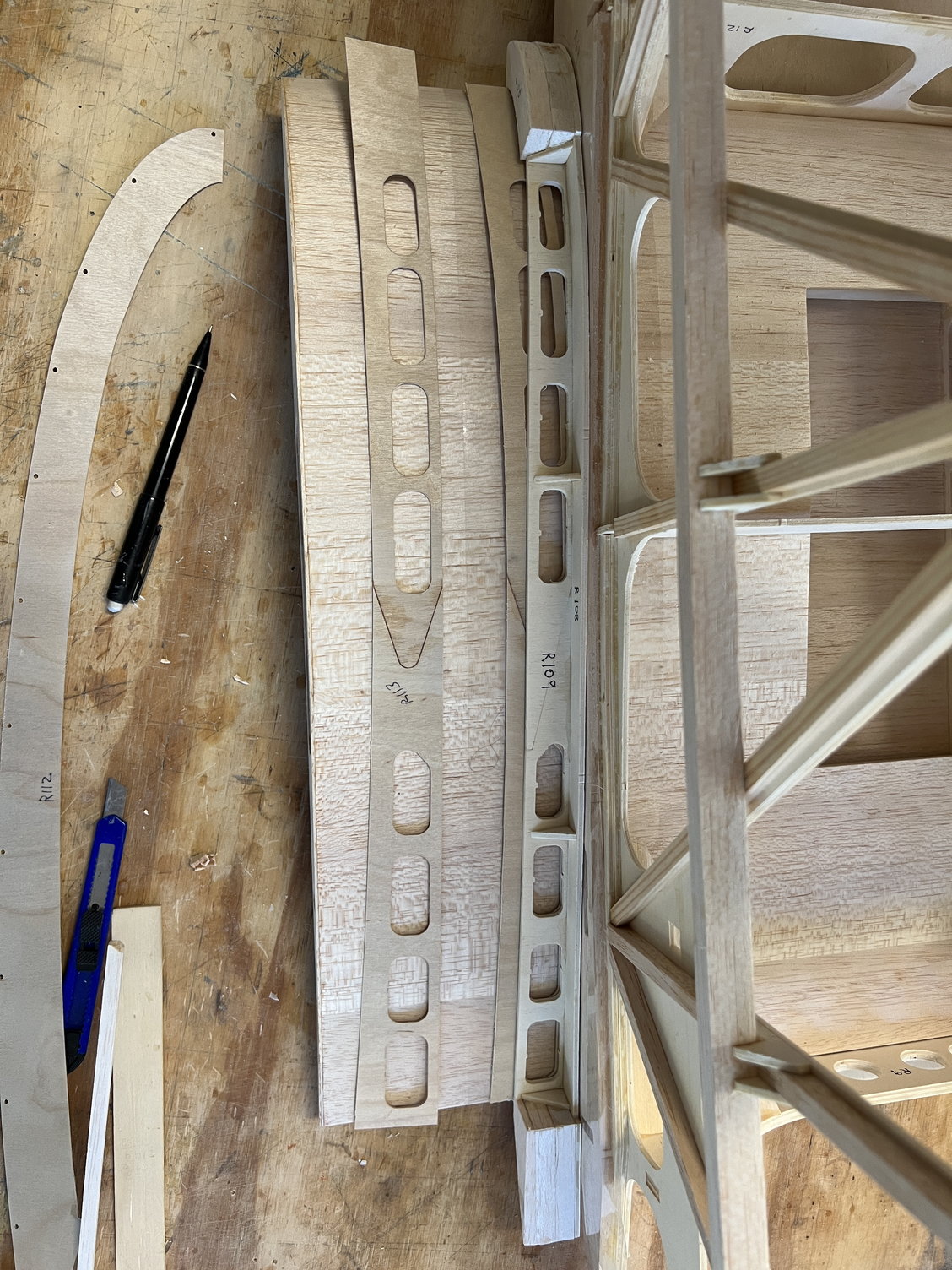
Okay, back to the wing fairings. So I gathered leftover .8mm ply and made a pattern to replace the unusable R113. I thinned out the front 1.5 inches of them to allow them to bend around the leading edge easier.
Once complete, the instructions say to "bolt R112 to the fuselage and slip 113 underneath before gluing on the fairings. However, I found that I wanted R112 sitting ON TOP of R113 so I taped 113 down to the wing then superglued 112 on top of it. After they were joined (and taped in place) I liberally (thick) CA'd all the fairing surfaces and squished them into place and held on for a few minutes. After filling with the balsa filler in the picture (which is the BEST stuff ever) they look and fit great.

Finished fairing before mounting.
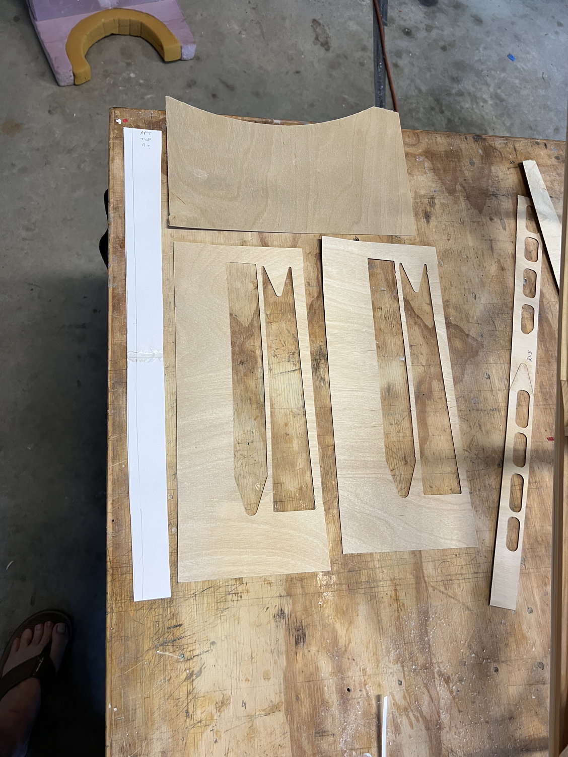
Here's the 113 pattern and scrounged wood
One completed 113. Be sure to thin the forward inch or two the bend around the leading edge
112 glued ON TOP of 113. Tape it all down and glue on the fairing.
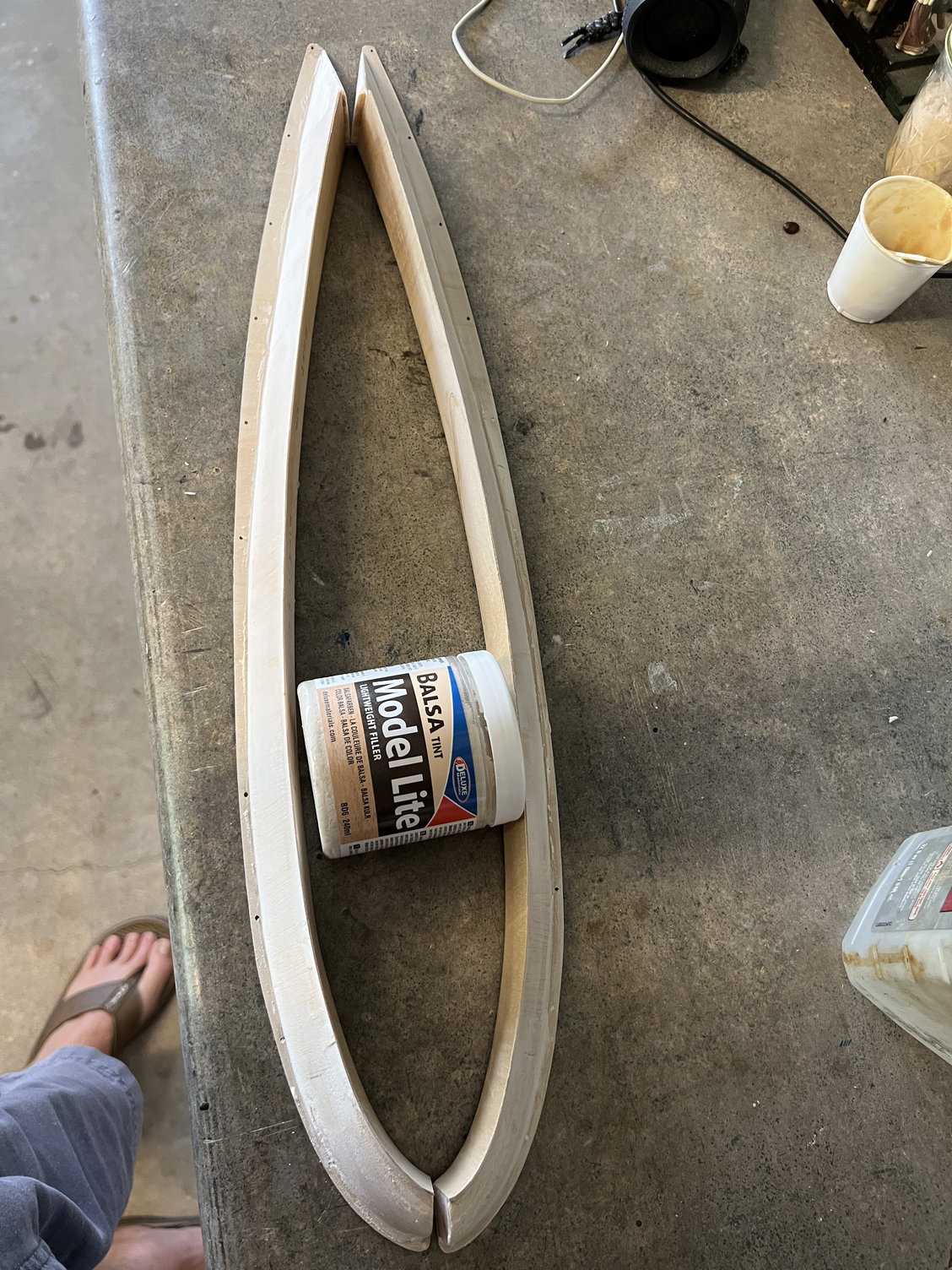
The (unsanded) fairings and the worlds BEST balsa filler. I will now sand and finish glass them with 3/4oz glass cloth and finishing resin.
Once complete, the instructions say to "bolt R112 to the fuselage and slip 113 underneath before gluing on the fairings. However, I found that I wanted R112 sitting ON TOP of R113 so I taped 113 down to the wing then superglued 112 on top of it. After they were joined (and taped in place) I liberally (thick) CA'd all the fairing surfaces and squished them into place and held on for a few minutes. After filling with the balsa filler in the picture (which is the BEST stuff ever) they look and fit great.
Finished fairing before mounting.
Here's the 113 pattern and scrounged wood
One completed 113. Be sure to thin the forward inch or two the bend around the leading edge
112 glued ON TOP of 113. Tape it all down and glue on the fairing.
The (unsanded) fairings and the worlds BEST balsa filler. I will now sand and finish glass them with 3/4oz glass cloth and finishing resin.
Last edited by mitchilito; 06-27-2022 at 04:33 AM.
The following users liked this post:
Steve (07-01-2022)
The following users liked this post:
Steve (07-01-2022)
") 06-28-2022, 04:24 AM
06-28-2022, 04:24 AM
#90
NEWS FLASH!! All builders out there in Bucker land, disregard the last half dozen posts!!
Embarrassing, but I made a mistake in the execution of the wing fairings. Unfortunately I didn't refer to the plans carefully before starting this step. There is a fairing detail that would've helped me (and you) in the plans. I've attached a pic of it: the fairing detail is in the bottom right corner. I'm really going to have to start referring to the plans more often!! This is also why my R113 wouldn't fit. With properly sanded saddles it should be close.
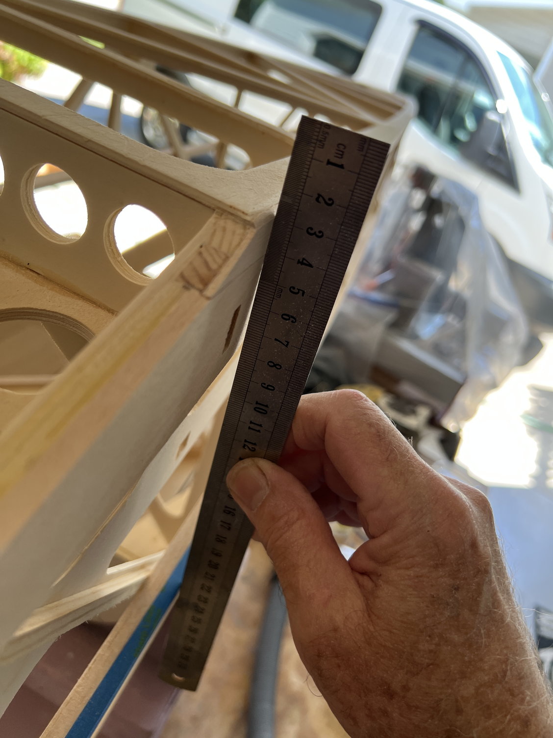
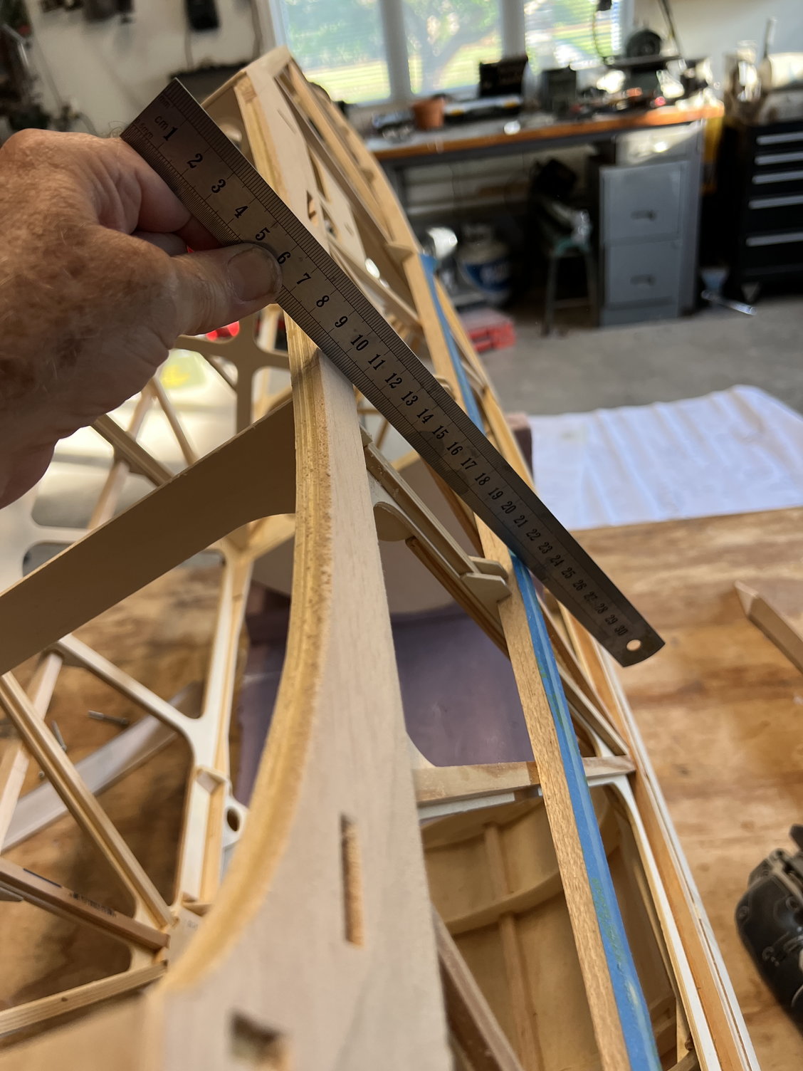
So here are the (hard learned) lessons on how to approach this process: first and foremost, start by sanding the bottom wing saddle to the cloth fall line. I did sand the front and back when I put the fill in there but the whole saddle needs to follow the fall line or the saddles will be pushing on unsupported cloth once covered etc. I've also attached a pic of how you will check the fall line to make sure it's perfect. I'm lucky because I can still sand my saddle to the cloth fall line without any outward appearance in my wing fairing fits. I will have a small empty space in the bottom inside corner behind my fairings which will not be a problem at all. The fairings are very robust and securely screwed down so it will be just fine. Other than this, your fairing assembly will be the same.
Yes, this build is what I would call "experts only" and apparently, I'm not quite and expert. I might be though, once I finish this thing!
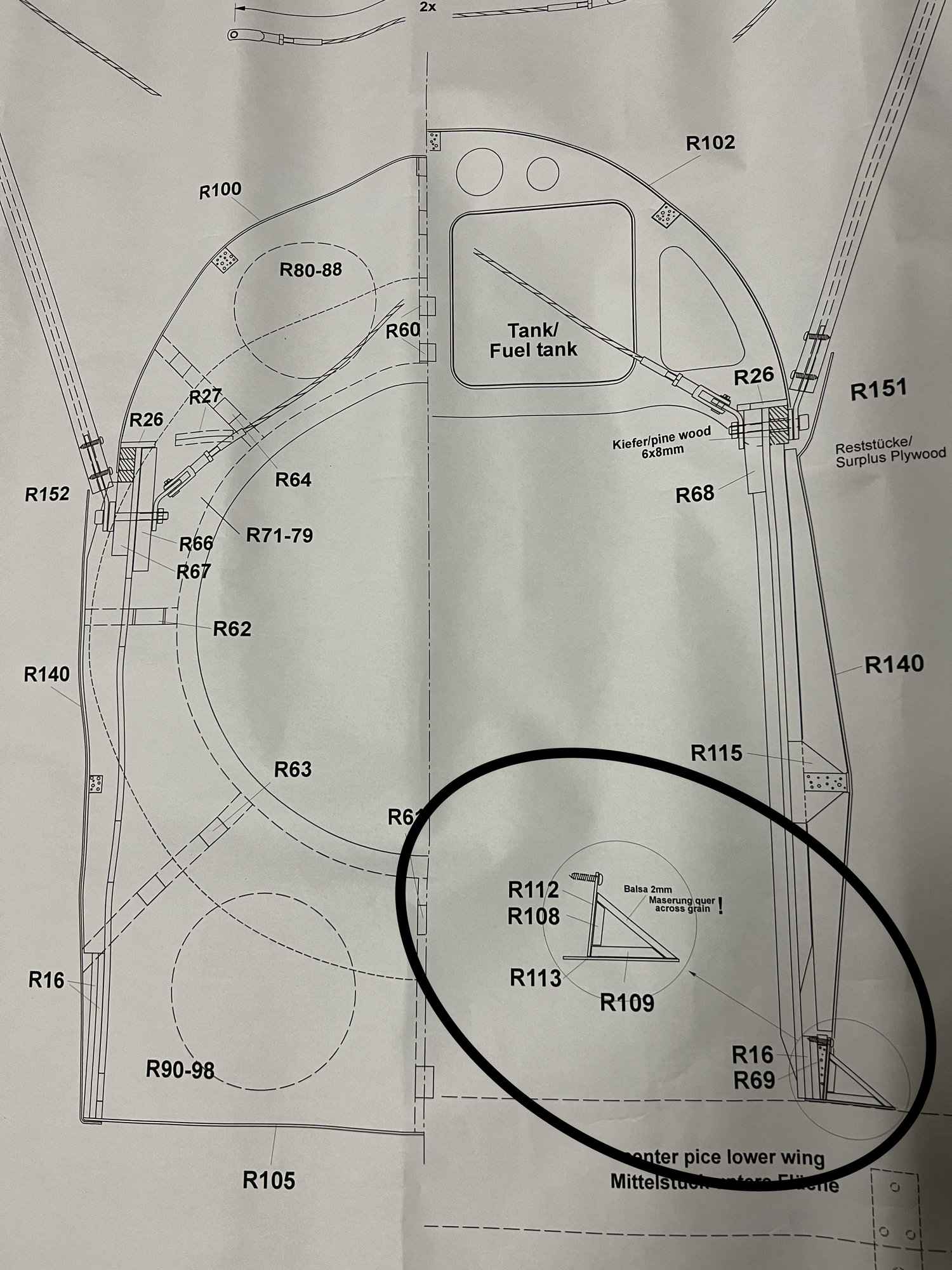
Embarrassing, but I made a mistake in the execution of the wing fairings. Unfortunately I didn't refer to the plans carefully before starting this step. There is a fairing detail that would've helped me (and you) in the plans. I've attached a pic of it: the fairing detail is in the bottom right corner. I'm really going to have to start referring to the plans more often!! This is also why my R113 wouldn't fit. With properly sanded saddles it should be close.
So here are the (hard learned) lessons on how to approach this process: first and foremost, start by sanding the bottom wing saddle to the cloth fall line. I did sand the front and back when I put the fill in there but the whole saddle needs to follow the fall line or the saddles will be pushing on unsupported cloth once covered etc. I've also attached a pic of how you will check the fall line to make sure it's perfect. I'm lucky because I can still sand my saddle to the cloth fall line without any outward appearance in my wing fairing fits. I will have a small empty space in the bottom inside corner behind my fairings which will not be a problem at all. The fairings are very robust and securely screwed down so it will be just fine. Other than this, your fairing assembly will be the same.
Yes, this build is what I would call "experts only" and apparently, I'm not quite and expert. I might be though, once I finish this thing!
Last edited by mitchilito; 06-29-2022 at 01:40 AM.
07-01-2022, 02:05 AM
#91
As I've said before, I don't plan to use the factory method of bent-up strut covers on the cabanes. Here's a full-scale example the doesn't have them. This is what I will recreate. I was lucky and found (at Lowes home improvement) a 24x36 inch sheet of the exact same gauge (.020") of aluminum provided by JW for a mere $20 so I'll be able to me a lot of mistakes!!
I will be copying this paint scheme on my model.

While I"m at it let me add this invaluable Full-Scale Bucker website:
https://sbeaver.com/Bucker/
I will be copying this paint scheme on my model.
While I"m at it let me add this invaluable Full-Scale Bucker website:
https://sbeaver.com/Bucker/
Last edited by mitchilito; 07-01-2022 at 02:58 AM.
07-02-2022, 10:48 AM
#92
Now for some GREAT news! I’ve been dreading fitting the forward aluminum plate that has to cover that complicated hole, bottom front.
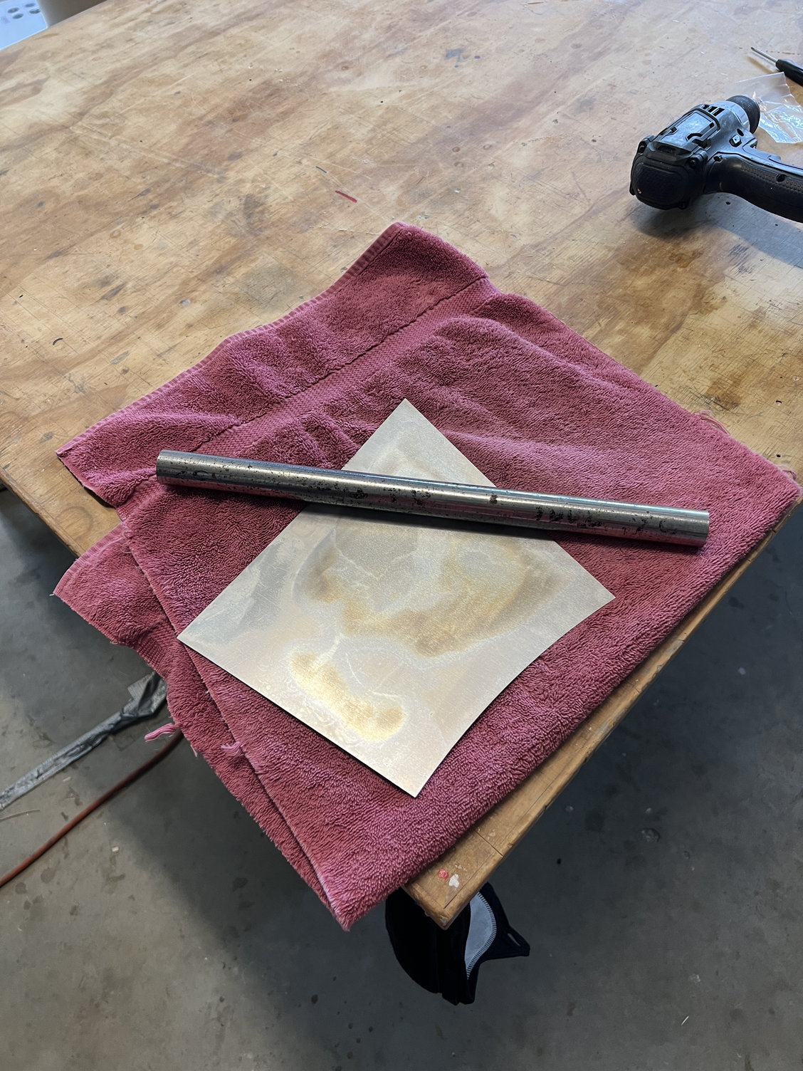
To make a long story short it was an absolute piece of cake. As impossible as it seems, this plate has almost zero compound bend anywhere on it.
You’ll see that I put the plate on a towel on the bench and used a 1” steel rod as a rolling pin (hey, I just realized an actual roll pin would be PERFECT) and pressing quite hard at times rolled each corner to varying degrees. The forward bottom corner takes the most but they all need some. I am so happy this was so easy because I’ve been dreading it.
As for the large side plates, you are going to need some serious sheet metal forming skills. I do not have those skills so I will pursue a different course as discussed.
Last edited by mitchilito; 07-03-2022 at 12:56 AM.
The following users liked this post:
Steve (07-02-2022)
07-04-2022, 03:50 PM
#93
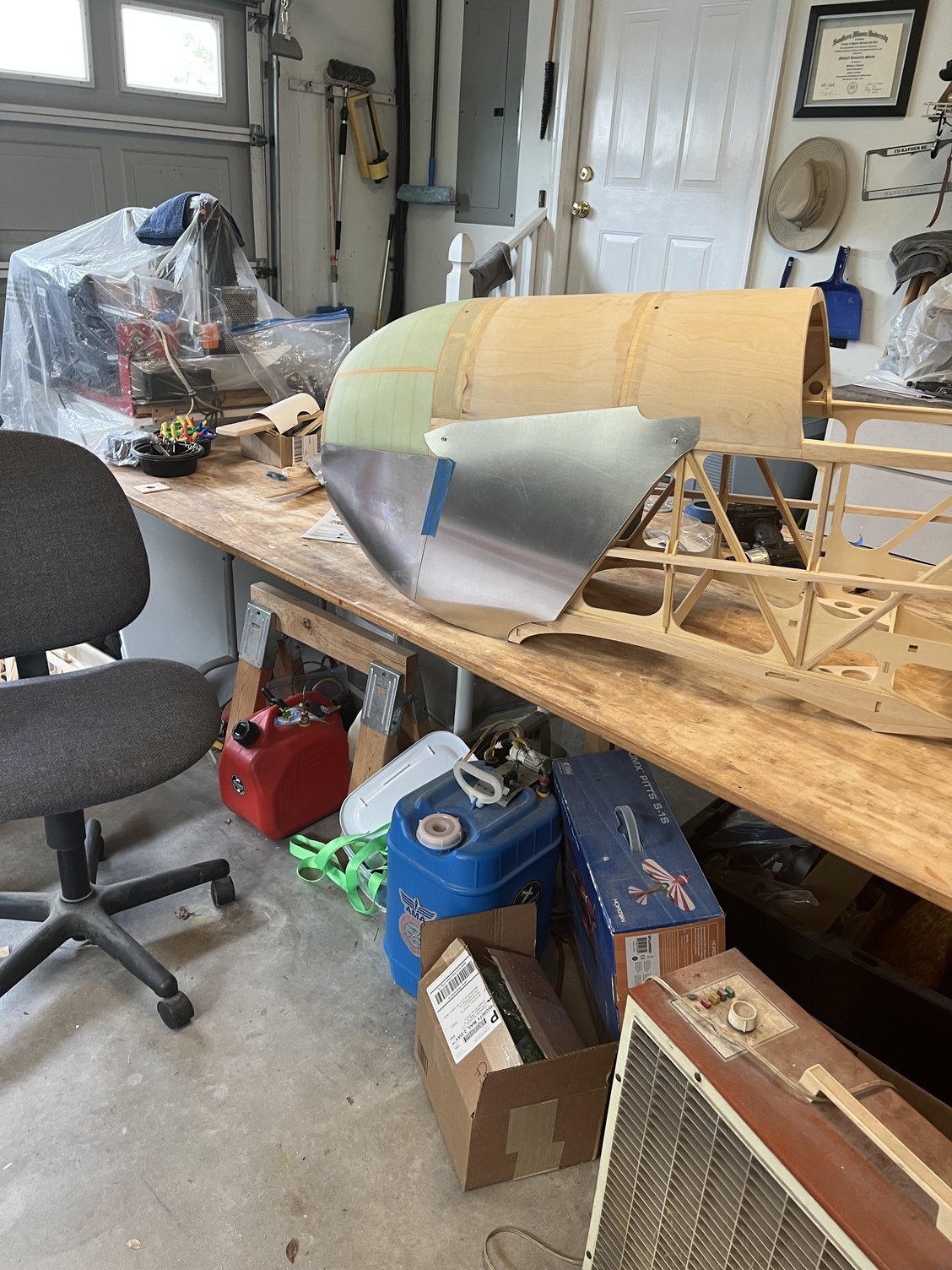
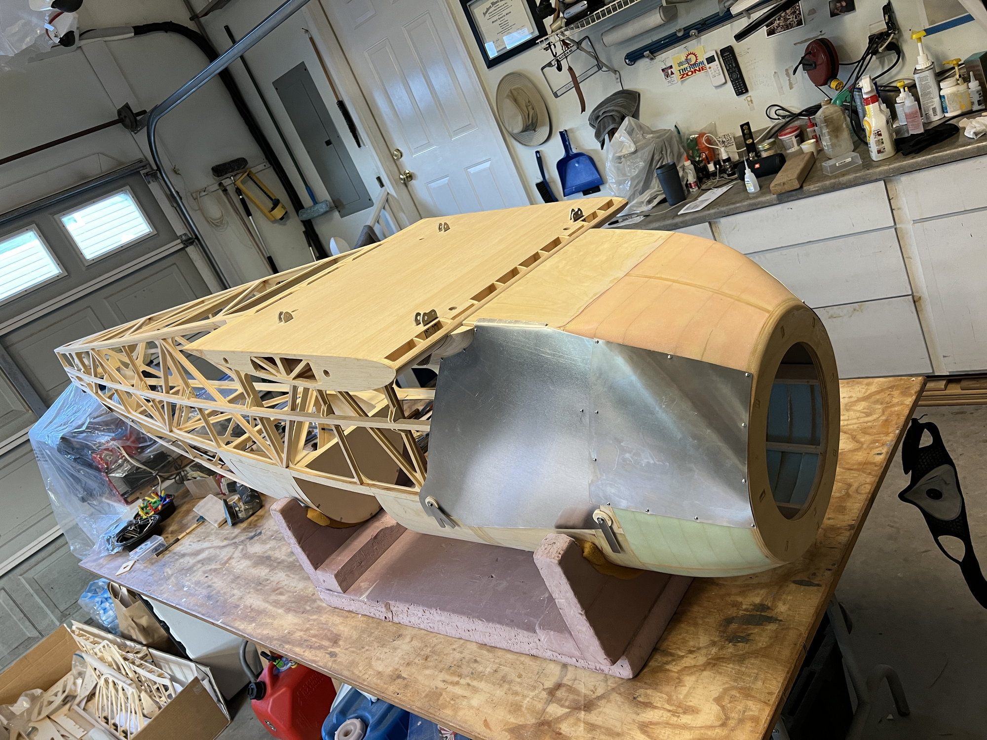
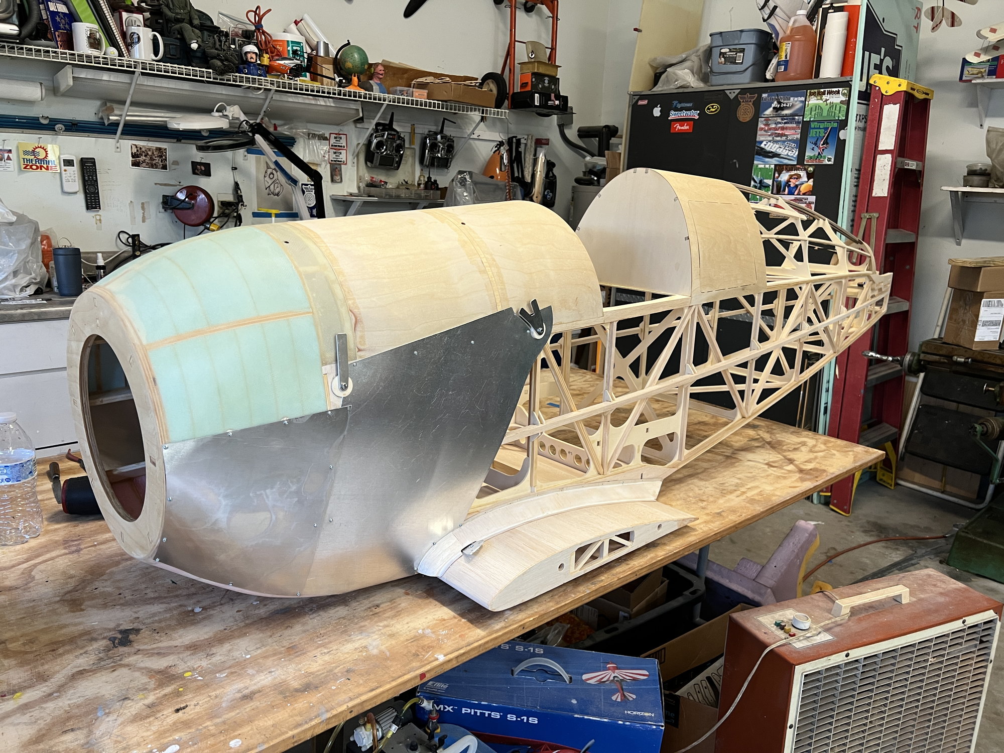
I'm really liking the way the sheetmetal work is turning out. I made two new big side plates and I'm happy with them. I wanted the front panel to lap over the big panel behind it (ala full-scale methodology) so I proceeded with that in mind. In the pics I haven't cut the metal out under the temporary plywood discs you see on the strut mounts but I will. There will be slight clearance all around. This allows me to remove the panel without removing the struts. Also, I'm not sure what the plans intended but I lapped the big metal panel OVER the wing faring mounts bottom front. I just love the way that worked out.
I'm attaching a pic of a Bucker that has the exact metal features around the strut mounts that I'm duplicating.
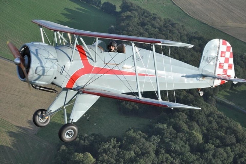
I'm attaching a pic of a Bucker that has the exact metal features around the strut mounts that I'm duplicating.
Last edited by mitchilito; 07-04-2022 at 04:30 PM.
07-05-2022, 11:32 AM
#94
Sheetmetal work is done. I have to commend JW for the design of this aspect of the kit. I would not have thought of it but it works well and allows a lot of internal access. It was an interesting process to get it all to work out. I started with the forward panels then added the rear panels. Like much of this kit you just need to keep "sneaking up" on the final assembly to get it all done (in the proper order). I learned a lot about working aluminum (!): the perfect tool was NOT an actual rolling pin but a 2x12 inch rod of bronze (and a double thickness of towel) I had kicking around.
Ready to receive 1/2" dowels
Doweled and sanded
Done: no strut covers
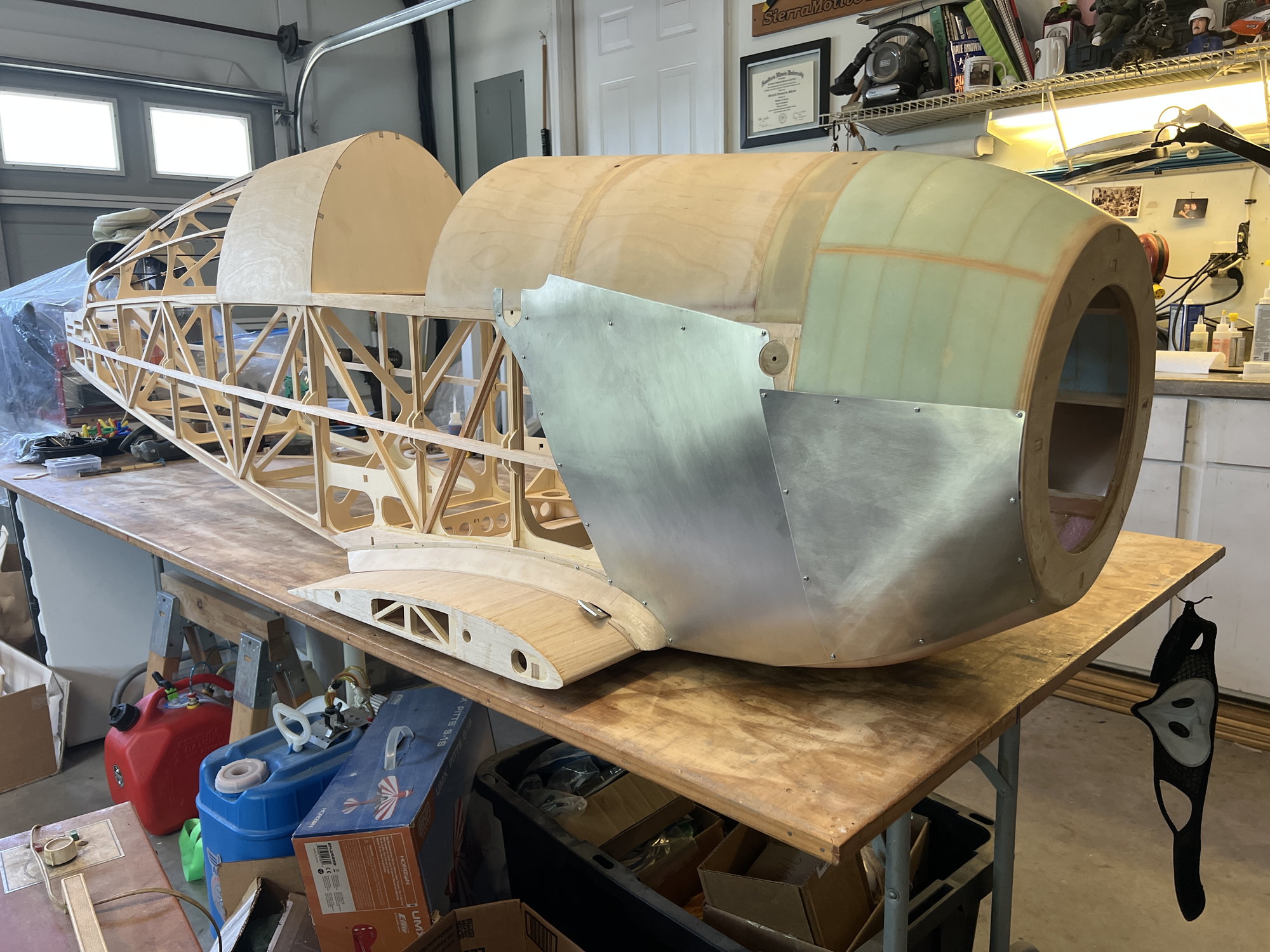
I'm very happy with the result.
Ready to receive 1/2" dowels
Doweled and sanded
Done: no strut covers
I'm very happy with the result.
Last edited by mitchilito; 07-05-2022 at 11:35 AM.
07-06-2022, 04:05 AM
#97
Quote: “Sheetmetal work is done. . . .”
HOT METAL WORKING TIP:
While I’m thinking of it, one thing that allowed all the panels to lay down flatter was going back after all the work was done and over sizing all the holes in the plates a fair amount. This allows them to float a bit and find the planes without binding. This solved a couple pesky buckles in my plates.
07-09-2022, 03:07 AM
#100
I picked this time to start working on the landing gear. The instructions have you doing it waaaay earlier in the build than this but for some reason I didn't want to. Doesn't really matter though . . .
There are a LOT of parts that make up the whole undercarriage. I found all of them in the box with the exception of the tailwheel shaft (maybe I'll find it later like I did some of the wood. . . .)
This kit uses flat plates as connectors that go into the ends of all the tubes. This leave voids in the ends of the tubes that I find absolutely intolerable. JW does provide WOODEN fillers for the big gear tubes, which I also would not use. My feelings on this subject are as follows: if it CAN fail, it WILL fail - especially on a highly stressed part of the aircraft like this landing gear. The whole assembly is going to be banged/torqued/twisted and generally abused its whole life and needs to be bulletproof. SO:
It would be difficult to build this gear without a machine shop but I guess it could be done. You could just use the flat plates but some parts have threaded rods that needs to screw into the tubes and there ares no provisions for this. I spent MANY hours machining parts to fill the tube voids and threaded rod sleeves.
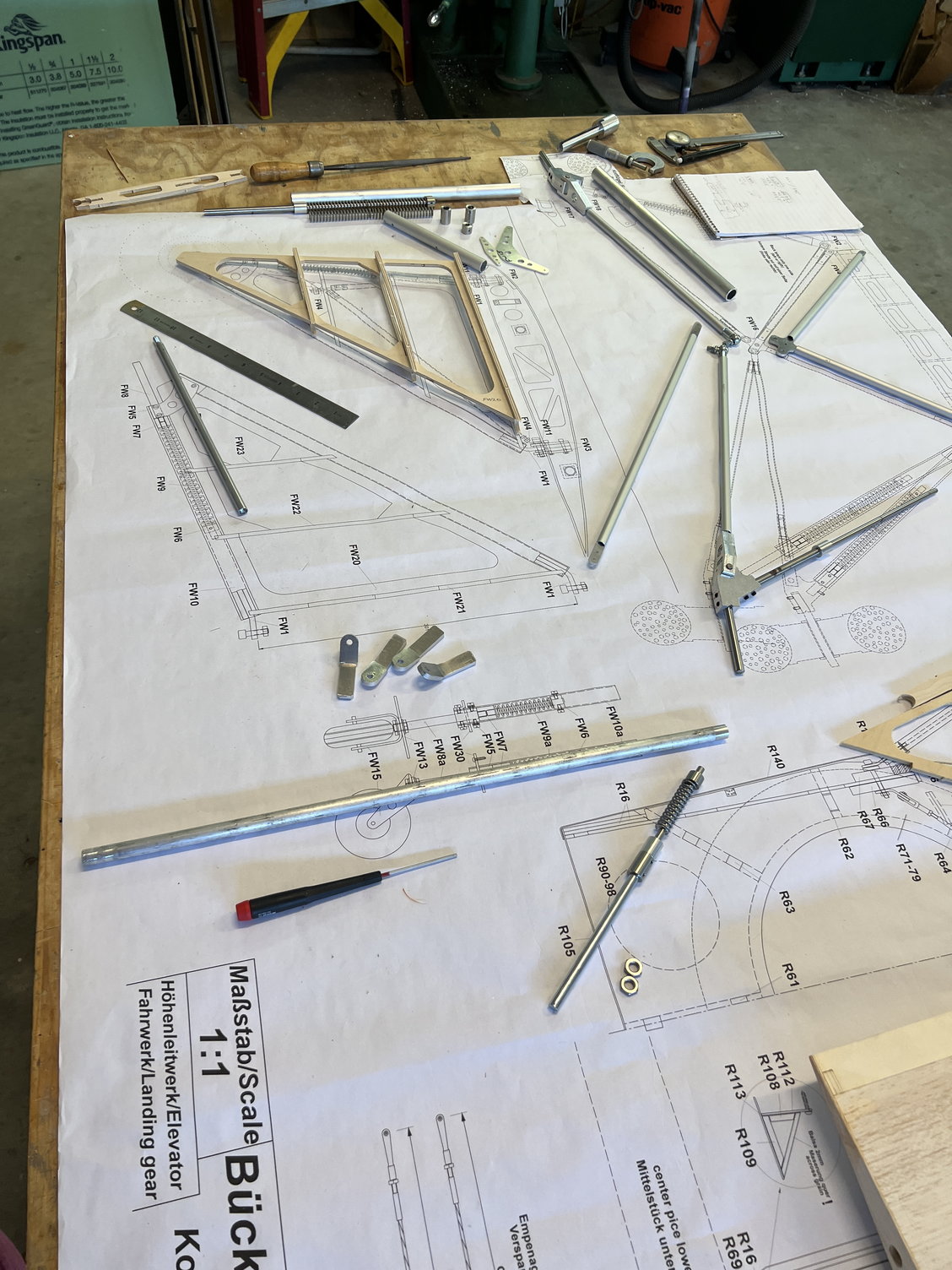
All the parts that make up the gear
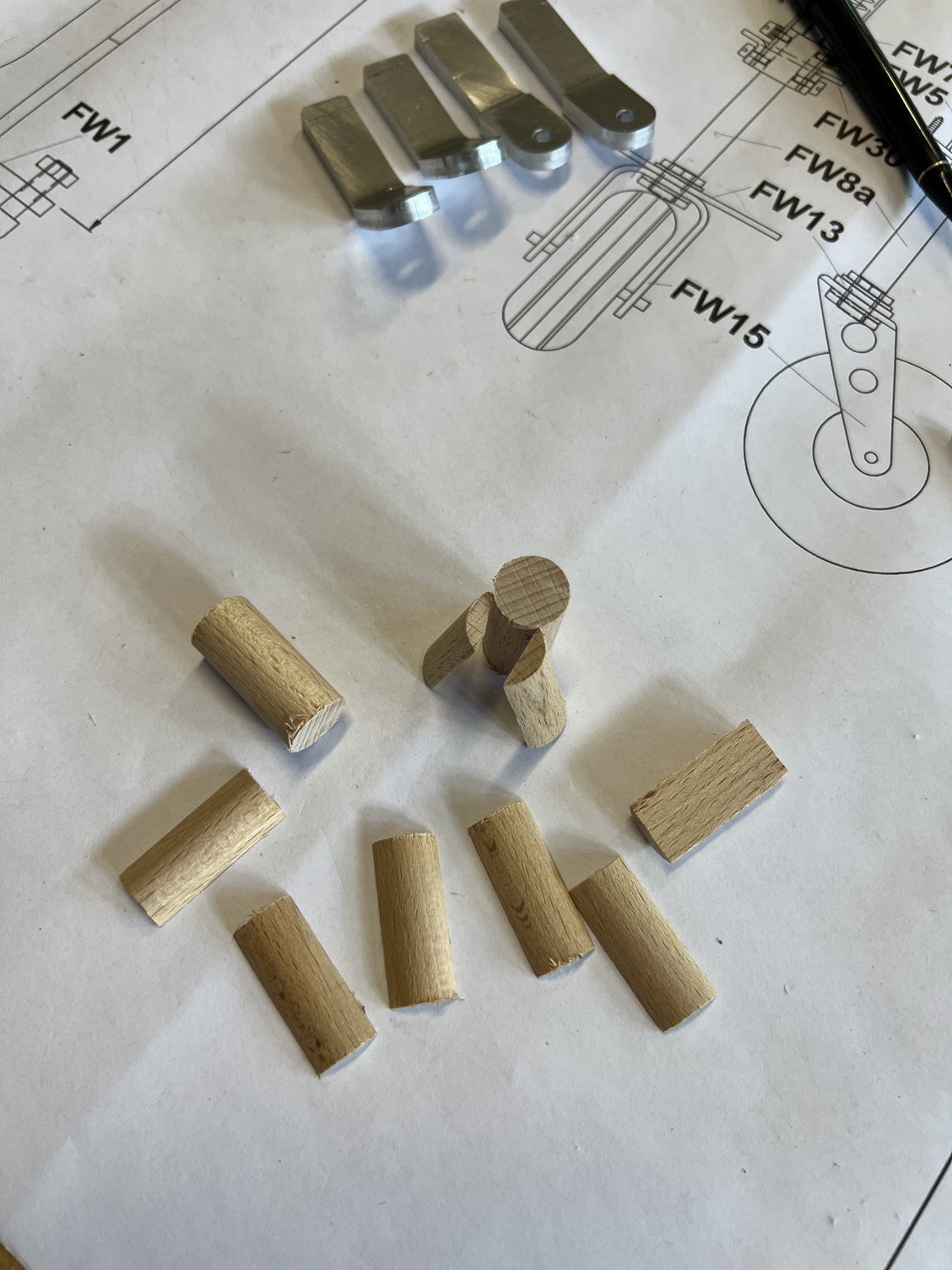
The provided wooden fillers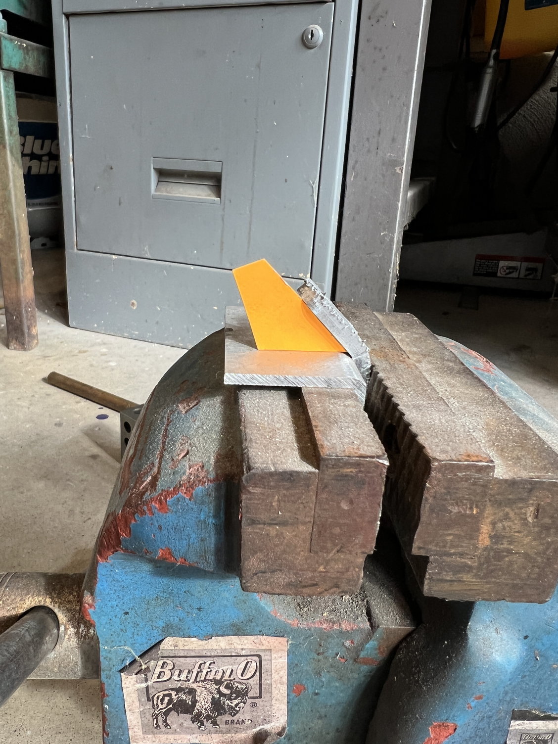
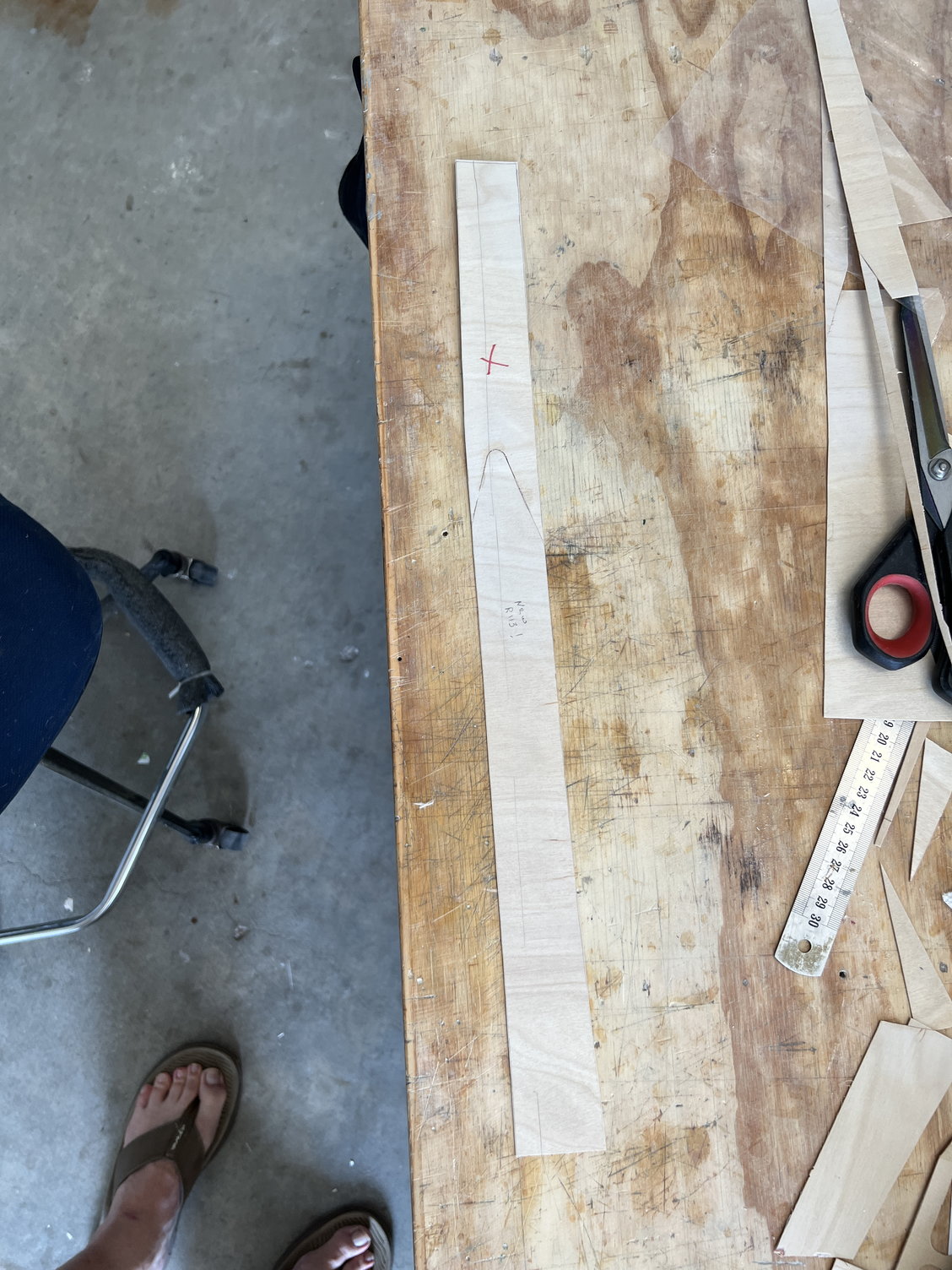
I made cardboard gauges for bending the big pieces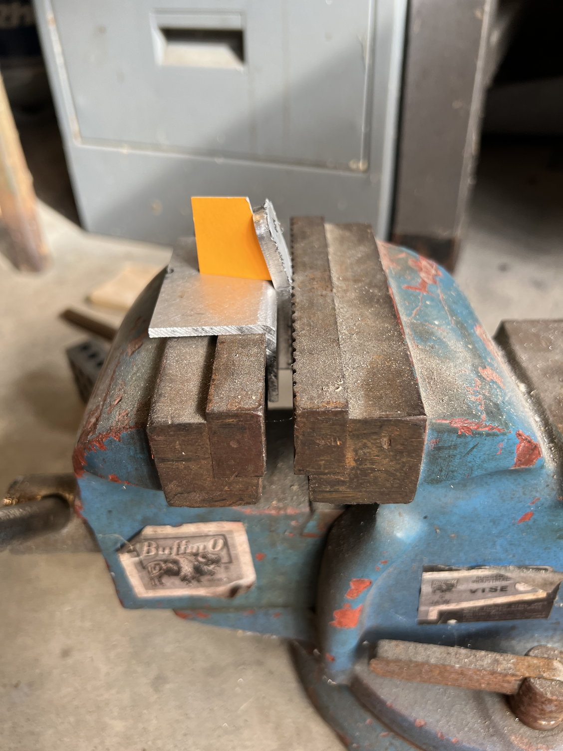
d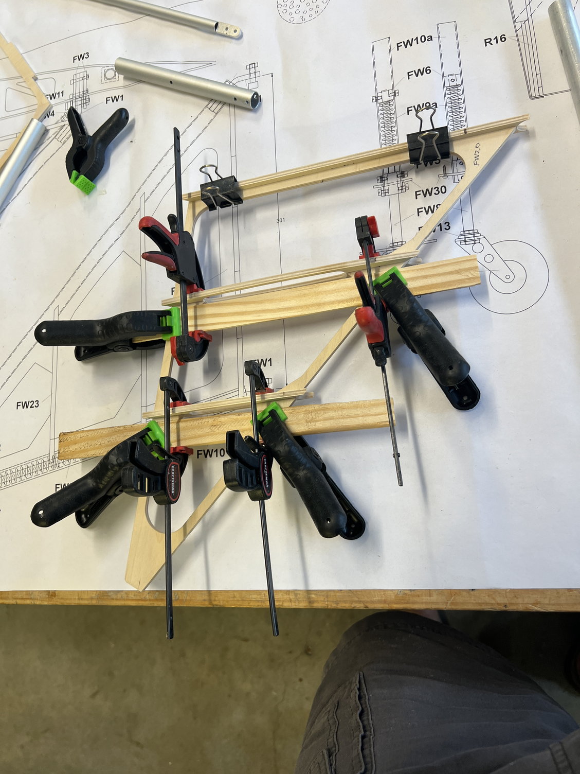
Gluing up the plywood parts. They need to have the tubes carefully fitted prior to this step, of course.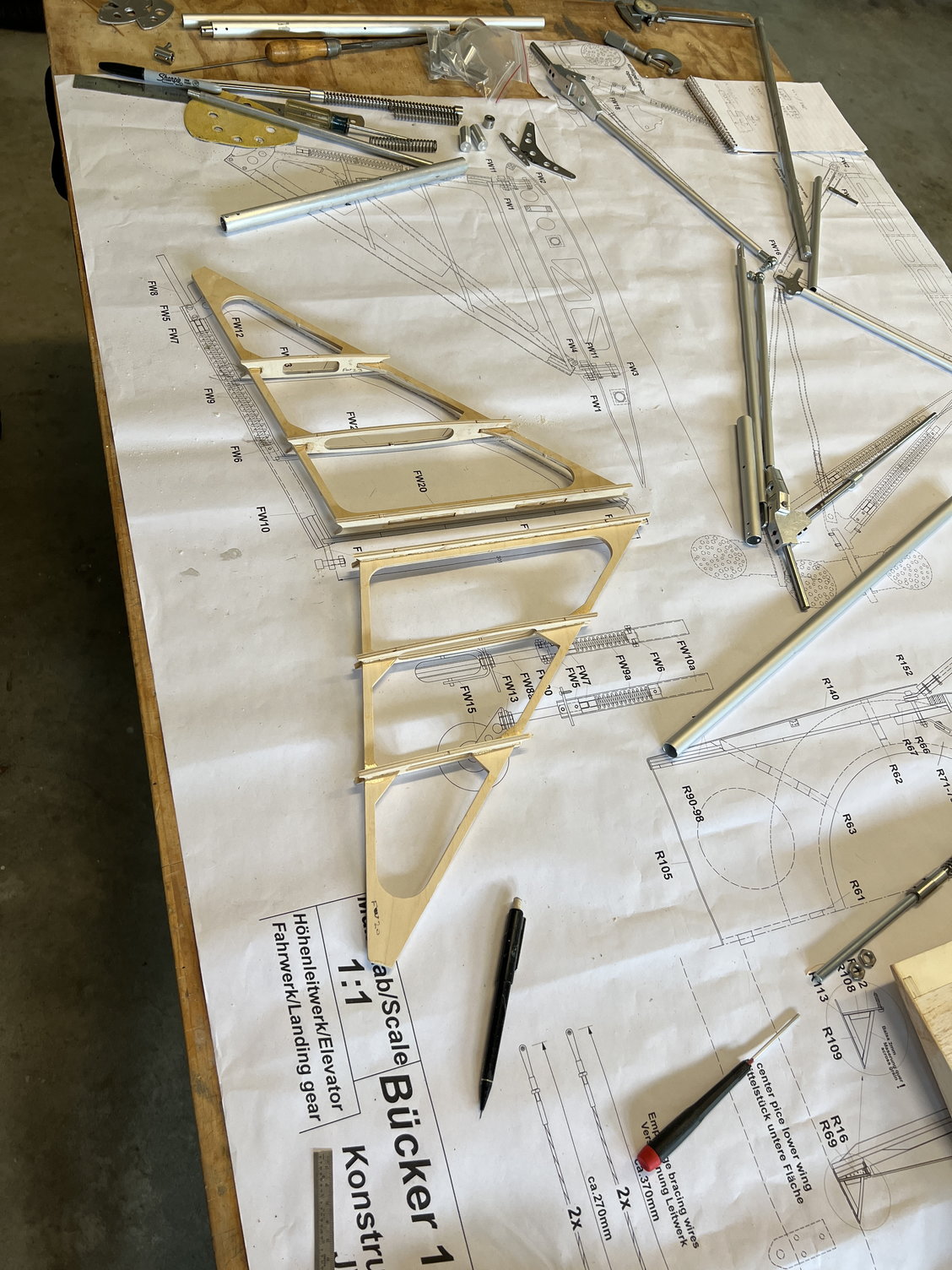
Done with the wood frames.
There are a LOT of parts that make up the whole undercarriage. I found all of them in the box with the exception of the tailwheel shaft (maybe I'll find it later like I did some of the wood. . . .)
This kit uses flat plates as connectors that go into the ends of all the tubes. This leave voids in the ends of the tubes that I find absolutely intolerable. JW does provide WOODEN fillers for the big gear tubes, which I also would not use. My feelings on this subject are as follows: if it CAN fail, it WILL fail - especially on a highly stressed part of the aircraft like this landing gear. The whole assembly is going to be banged/torqued/twisted and generally abused its whole life and needs to be bulletproof. SO:
It would be difficult to build this gear without a machine shop but I guess it could be done. You could just use the flat plates but some parts have threaded rods that needs to screw into the tubes and there ares no provisions for this. I spent MANY hours machining parts to fill the tube voids and threaded rod sleeves.
All the parts that make up the gear
The provided wooden fillers
I made cardboard gauges for bending the big pieces
d
Gluing up the plywood parts. They need to have the tubes carefully fitted prior to this step, of course.
Done with the wood frames.
Last edited by mitchilito; 07-09-2022 at 03:17 AM.