


NGH 38CC 4 stroke
 06-02-2019, 01:54 AM
#1626

Join Date: Jan 2007
Location: Dubai, UNITED ARAB EMIRATES
Posts: 500
Likes: 0
Received 2 Likes
on
2 Posts
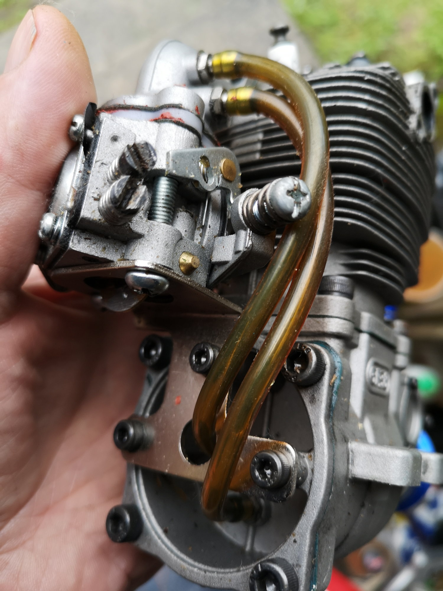
I shamelessly stole someone elses picture from this thread, justo illustrate.
If you follow the red arrows....that isunregulated air. There is a possibility they could have factored this in to the air/fuel mix, but that would not hold true through the rev range.

I saw someone else put a T-piece from the breather nipple at the bottom to one of the other tubes going to the manifold....I could see how this would stop the unregulated air, but it would put the crankcase at negative pressure. That could be a good thing, but it would also require the draining of the crankcase from time to time as the engine is unlikely to reprocess all that oil. It could also result in the oil ratio to be dropped...
What do you guys think?
If you follow the red arrows....that isunregulated air. There is a possibility they could have factored this in to the air/fuel mix, but that would not hold true through the rev range.
I saw someone else put a T-piece from the breather nipple at the bottom to one of the other tubes going to the manifold....I could see how this would stop the unregulated air, but it would put the crankcase at negative pressure. That could be a good thing, but it would also require the draining of the crankcase from time to time as the engine is unlikely to reprocess all that oil. It could also result in the oil ratio to be dropped...
What do you guys think?
 06-02-2019, 07:03 AM
#1627
Thats the supercharger man!!! It is probably more for idle than anything else. They probably added the second one after they found the sump one filled with oil and caused oil to blow out the lower vent which is meant for intake air. I'll bet they intended for this engine to be a clean runner and not leave oil goo on the plane that would happen if they just vented the case to atmosphere like others do.
I have two of these NIB that I bought for my B-25 and found they are too big, would have to really open the cowls for them to fit, and replaced them with a pair of Saito FG-30. These wi more than likely go into my someday to be built P-61 Black Widow. Now that I have an engine test stand, I plan to run these up and see how they do.
I have two of these NIB that I bought for my B-25 and found they are too big, would have to really open the cowls for them to fit, and replaced them with a pair of Saito FG-30. These wi more than likely go into my someday to be built P-61 Black Widow. Now that I have an engine test stand, I plan to run these up and see how they do.
06-02-2019, 11:41 AM
#1628
Join Date: Jan 2007
Location: Dubai, UNITED ARAB EMIRATES
Posts: 500
Likes: 0
Received 2 Likes
on
2 Posts
Supercharger....lol!
It could be a cleanburner! The lower of the backplate nipples will always collect oil, its lower than the breather in the upright mounting position....inverted, and all bets are off.
I think the pipes should be swapped, and then the T-piece from the breather, into the lower nipple on the backplate...then this engine will just recirculate oil. It doesnt matter either way but maybe drain the engine from time to time if there is excessive oil, but if you keep the ratio at 30:1 or 35:1 possibly, it will be getting good lube from the recirc.
Inverted engines are always going to have the problem of oil collecting in the plug if it isnt stored upright or on its side...
...the big thing though for me, is that as it is now, there IS unregulated air getting in.....and we dont like unregulated air....
Waiting to see of my local HS is getting them in soon.
Would love to see the B-25 project acdii.....any links to build/vids?
 06-09-2019, 08:53 PM
#1631
Join Date: Jul 2009
Location: N. Central Fla.
Posts: 21
Likes: 0
Received 0 Likes
on
0 Posts
The tubes pictured in post 1626 are not connected correctly , the carb pulse tube goes to top center backplate , the lubrication tube connects from top on intake manifold to bottom connection on backplate, as per NGH schematic instruction sheet. Now, I just replaced my wiped out cam lobe cam ,lifters finally on the way, what caused it ? I broke the engine in upright mounted per instructions , but with about 2 hours test stand time over a week off & on. Was guilty of hitting 8000 rpm shortly (which probably started the valve float that started the lifters hammering the cam lobes , but didn't know it at the time ! , MAYBE?) Mounted it inverted in my seagulls spitfire (comes with crappy retracts for your total enjoyment experience) & flew about an hour's worth of 12 minute flights over a couple sessions ,then started noticing clicking sound at idle & power dropping off drastically. Good Compression disappeared , disassembled & found cam damage. It looked exactly like an earlier post in this thread. I did notice when the old lifters were reinstalled without the cam installed, there was stickshun when moving the lifter up & down in it's bore, both of them. A few lite passes of lubed 2000 grit wet dry & wood dowel smoothed it's travel .We'll see how the new lifters feel when they arrive from China. My buddy said I should have broken it in with 15 to 20 % instead of the 35% NGH says to use, I don't know? Gonna be more cautious with it. Hope this helps, Ed
06-10-2019, 04:16 AM
#1632
Join Date: Jan 2007
Location: Dubai, UNITED ARAB EMIRATES
Posts: 500
Likes: 0
Received 2 Likes
on
2 Posts
Ed! We meet again! lol
Thats a little nerve wracking to hear about the lifters! When/if I get one of these, I will keep an eye out for that. I am still a little confused how the open crankcase is not 'guilty' of supplying unregulated air... Maybe they expect the crankcase to be full of oil and not shlurping in air...I mean, if you disconnected that tube, the engine would not run well at all...
Maybe I am overthinking this....bu to me, any air AFTER the carburettor, is unregulated....perhaps its that little that it doesnt influence it....
I never overthink retracts, I simply open my wallet, and buy Electron's. In percentages costs to run a plane, I work on:
Kit:20%
Engine: 30%
Retracts 20%
Electronics: 30%
...or something like that....
I very rarely use kit supplied retracts, and I dislike air, not because I have a preference, I just KNOW electrons well.
06-10-2019, 07:31 AM
#1633
Since I have several 4 stroke gas engines that all run 20% :1 oil, going to stick with it for the NGH as well. Oil doesn't hurt, just makes clean up a bit more tedious. Lack of oil OTOH leads to crap breaking.
Last edited by acdii; 06-10-2019 at 11:04 AM.
06-10-2019, 10:15 AM
#1634
20%Oil in gas?? Should be interesting to know the results.
Even on my glow four strokes I run 15-16 % and no more.
Saito gas four strokes recommend 1:20 mix that equates to roughly 5%oil . Most people use a 1:15 mix that equates to 6.66% oil mix (approx) and this is when Saito gas engines do not use big end bushing or bearing. NGH big end has rollers
Even on my glow four strokes I run 15-16 % and no more.
Saito gas four strokes recommend 1:20 mix that equates to roughly 5%oil . Most people use a 1:15 mix that equates to 6.66% oil mix (approx) and this is when Saito gas engines do not use big end bushing or bearing. NGH big end has rollers
 06-10-2019, 08:06 PM
#1637
Join Date: Jul 2009
Location: N. Central Fla.
Posts: 21
Likes: 0
Received 0 Likes
on
0 Posts
Yep, me too. I agree with mchandrayan and acdii . Post 1631 should read 15:1 to 20:1 instead of the 35:1 ratio . Percent sign incorrect .Sorry for the typo ,Thanks for the correction. That could really run somebodies oil bill up!
06-11-2019, 06:09 AM
#1638
Although on my Glow saito I do run 20% oil. Messy, but my engines run great. When I first ran up my FG-11, I saw no oil residue @ 20:1, to upped it to 16:1 for break in. I wanted to make 100% sure every moving part got some oil, and it worked. Now I run 20:1 and get some residue to confirm oil is getting where it needs to.
06-12-2019, 02:14 AM
#1639

From the instruction manual that came with my engine
Are you sure? As per manual the top nipple on intake connects to top nipple on the back plate and the bottom to bottom. Did they change the manual?
Last edited by mchandrayan; 06-12-2019 at 02:18 AM. Reason: Added picture
06-12-2019, 04:06 AM
#1640
Join Date: Jul 2009
Location: N. Central Fla.
Posts: 21
Likes: 0
Received 0 Likes
on
0 Posts
Very Interesting. I purchased my engine mid 2015 approx. from Hobyking . Go to their website, click our engine , click Upload Files, click Download [551] and you'll get the Official NGH GF38 Operators Manual. I wonder if mounting it inverted as I did cause the Lube Pipe to convert to a Vent Pipe ? Or does it stay oil misty enough to do the job.
06-12-2019, 04:44 AM
#1642
I searched online for the original manual and do see where you are coming from. The NGH manual does show what you are referring to. However, I got my engine from Just Engines in UK. And the instructions accompanying the engine is what I posted. I would rather trust Just Engines
06-12-2019, 09:43 AM
#1643
Join Date: Jul 2009
Location: N. Central Fla.
Posts: 21
Likes: 0
Received 0 Likes
on
0 Posts
Yes, with both backplate nipples so close together I really don't see how it makes any difference, unless one of them has a check valve in it.
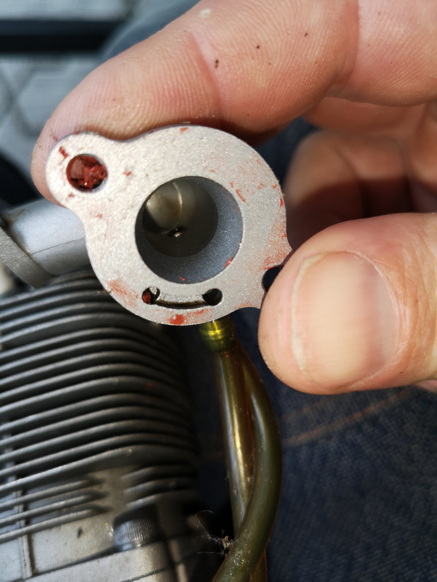
Cathurga, I seem to remember the tube, that you show with the red arrow , is always filled with oil when it's running and also when it's shut down ,so I wonder if that blocks what your concern is with the unregulated flow . It always looked like dark oil ( I used redline 35:1 ) in the tube which means it was traveling from crankcase to intake manifold, is my guess. Never really stood there and watched it flow while running, never really questioned it.
Next question, Is there a rpm rev limiter available for our size applications ? ANYBODY ? Cheers, Ed
06-12-2019, 12:00 PM
#1644
Join Date: Mar 2012
Location: , WI
Posts: 85
Likes: 0
Received 0 Likes
on
0 Posts
I don't think you see much airflow (especially compared to the intake manifold) from the nipples in the back plate to the intake manifold. The only air admitted to the crankcase is bloiwby from the piston/cyl.
While I am sure that there is a steady air movement from the cylinder there isn't the torrent of air moving thru the crank case that you see with a 2-stroke engine. I think you will have a better understanding of just what these nipples to if you think of the center backplate to carb connection as a pressure fluctuation line to operate the diaphragm type fuel pump in the carb (hence no air flow.) The nipple on the front bottom ot the crank case as a low pressure well to encourage some of blow by oil in the crank case to flow towards the front ball bearing (hence no air flow.) Finally think of the bottom nipple as a sump to collect excess blowby oil (if any) and a pcv (positive crankcase vent) connection to the middle of the intake manifold, If your engine has good compression there isn't really much of a supply of air to the crank case in the first place and compared to the diameter of the intake, not much air COULD pass through that oil clogged tube into the manifold. D.H.
While I am sure that there is a steady air movement from the cylinder there isn't the torrent of air moving thru the crank case that you see with a 2-stroke engine. I think you will have a better understanding of just what these nipples to if you think of the center backplate to carb connection as a pressure fluctuation line to operate the diaphragm type fuel pump in the carb (hence no air flow.) The nipple on the front bottom ot the crank case as a low pressure well to encourage some of blow by oil in the crank case to flow towards the front ball bearing (hence no air flow.) Finally think of the bottom nipple as a sump to collect excess blowby oil (if any) and a pcv (positive crankcase vent) connection to the middle of the intake manifold, If your engine has good compression there isn't really much of a supply of air to the crank case in the first place and compared to the diameter of the intake, not much air COULD pass through that oil clogged tube into the manifold. D.H.
06-12-2019, 01:15 PM
#1645
Another thing to consider is that the airflow that is moving through it is in pulses, same volume in as out with each stroke of the piston. Each down stroke moves the same volume as the up stroke. Top it off with the vacuum above the carb, it regulates how much oil is drawn out from the bottom nipple. If there was only one, then it would draw too much oil out and foul the plug. There is a constant vacuum being applied to the crankcase via those two nipples, and I believe one reason is to help draw fuel/oil up from the intake, through the valve guide, to help lubricate the rockers, this way there is lube coming from both ends. The exhaust rocker gets it's lube from the exhaust pressure. The lifters gets it's lube from the crank case, and some draw down from the rockers. Visualize this. The piston is on the upstroke, creating vacuum in the crank, which is already in a vacuum, the intake valve is closed, vacuum is drawing on the rocker side of the intake valve via the crankcase, but no vacuum is in the intake, so a bit of oil/fuel gets drawn up around the valve stem. Multiply that by 1000 when idling at 2000 RPM. The bottom nipple is open to atmosphere to help regulate on the downstroke so that it remains constant and eliminates any pulses in the intake.
One other thing to note, the Walbro style carb on a 4 stroke is not like that on a 2 stroke, it doesn't use crank case pulses to operate the fuel pump, instead it uses intake vacuum. They accomplished this by adding a spring to the diaphragm. When the intake is closed, vacuum drops enough for the spring to return the diaphragm.
On my other 4 strokes, Saito, I have the breather connected to a brass tube that is bent to follow the contour of the muffler with the end cut at 45 degrees right behind the exhaust opening. It acts as a scavenging system and helps pull waste oil out of the crankcase. Since it has only one opening, the pulses from the piston doesn't allow the oil to come out until the engine is stopped. By having the exhaust create a vacuum behind the 45 opening, it draws out the oil accumulating in the line, while still allowing air back into the tube with the upstrokes. The NGH is doing something similar by using the intake.
06-12-2019, 10:53 PM
#1646
Join Date: Jan 2007
Location: Dubai, UNITED ARAB EMIRATES
Posts: 500
Likes: 0
Received 2 Likes
on
2 Posts
Yeah, wht DH and acdii have said makes total sense. I was 'assuming' that there was an open circuit in the crankcase, which is not the reall case, in fact the breather nipple at the bottom, is between the bearings as well, and in combination of the varying crankcase pressures on the up and down strokes, its not likely easy for air to influence the manifold pressures. I was overthinking it, and along with your explanations, it makes sense.
I will get my engine hopefully at the end of the month, and would be good to know the RIGHT way to connect those tubes. One thing that is not clear is how the lower nipple on the manifold works. From the exterior look of where the nipple connects, it appears to be open to the pulse port on the carb, as well as being open to the manifold? Is this the case or is it only open to the pulse port?
I have never noticed any difference between 4T and 2T Walbro carbs, but then, I havent opened one up. It makes sense to have the diaphragm assisted by a spring opposing the pulses, rather than just pulses.
Frankly, I dont think Saito pay enough attention to their gas engines, they would benefit from the sort of set up you see on this engine, rather than just upping the oil ratio so that 'blow-by' is lubing the crankcase and valve mechanisms.....it means trying to burn more oil, and in my FG60R3 and FG40, running on the 20:1 mix has fouled my plugs, and the ex valve is all carboned up. I have recently converted to Stihl oil to try and reduce this. On the FG40 I dont have an option to reduce the oil ratio. On the FG60 I have modified to run fuel/air through the crankcase, and am now running it on 30:1. It seems happier this way, but not going to call it a success until some run time has bene completed.
Sadly, the FG40 this is not an option, but if this NGH38 works well enough on this design, I might look to do something similar with the FG40....its just a few nipples really...and the cost of a manifold and backplate if it fails and has to be converted back. Hell, even just plugging the holes you have made would reverse the mod. This is why I am keen to know how that lower nipple is open to manifold AND pulse port OR just the pulse port.
Thank you for the updates, info and insight....I am known to run out of talent and knowledge, so getting others input is great!
Andy
 06-13-2019, 12:53 AM
#1648
Join Date: Jan 2007
Location: Dubai, UNITED ARAB EMIRATES
Posts: 500
Likes: 0
Received 2 Likes
on
2 Posts
Tyor,
Thats reassuring, hopefully I will have similar success!
If those tubes are both open to the inlet manifold, then I dont think it really matters which one is connected where....I will say though, potentially having oil dumping into the carb's impulse port, is a little unnerving. Considering you have had good reliability, it seems fine.
BTW, what oil are you using, and at what ratio?
Regards
06-13-2019, 02:12 AM
#1649
It is som many rumours about this so to explain a bit I opened the manifold. The tube closest to the carburettor only goes to the hole of the pump. the other tube is open into the manifold. I have used biffrent brands of oils. I think any full syntethic for air cooled 2stroke engines will work. Ratio is 30:1.
from 5:30 in this video is my black horse 2.85meter fieseler storch with ngh 38cc
from 5:30 in this video is my black horse 2.85meter fieseler storch with ngh 38cc
06-13-2019, 02:39 AM
#1650
The reason Saito uses 20:1 is because they are converted glow engines. The NGH is designed from the ground up as a 4 cycle gas. Interesting to see that there is a port to the pump, so maybe NGH figured out how to use it to drive a 2 stroke pump. Usually there is not enough pressure in the crank on a 4 stroke to push the diaphragm all the way back, or maybe they are using spring assist as well, but also surprised there is no oil accumulating. I will have to take mine apart and study it.