


View Poll Results: Should I omit the two front Glacis Hatches for a Combat Vehicle?
Yes, remove the Hatches.


3
42.86%
No, keep the Hatches.


4
57.14%
Voters: 7. You may not vote on this poll
1:16 Versuchsträger VT 1-2
 08-26-2022, 04:47 PM
#1

Thread Starter

So, with my E-100 almost finished I decided to pick up a new project and what better something "easier" because of reusable parts like Tracks, Wheels, and Stuff from a Commercially available RC Model? 😁
The Versuchsträger VT 1-2:
Like with my E-100 a 1:35 Scale Model will be used as a reference for picking up the Dimensions - In this case the recently released TAKOM #2155 VT 1-2:
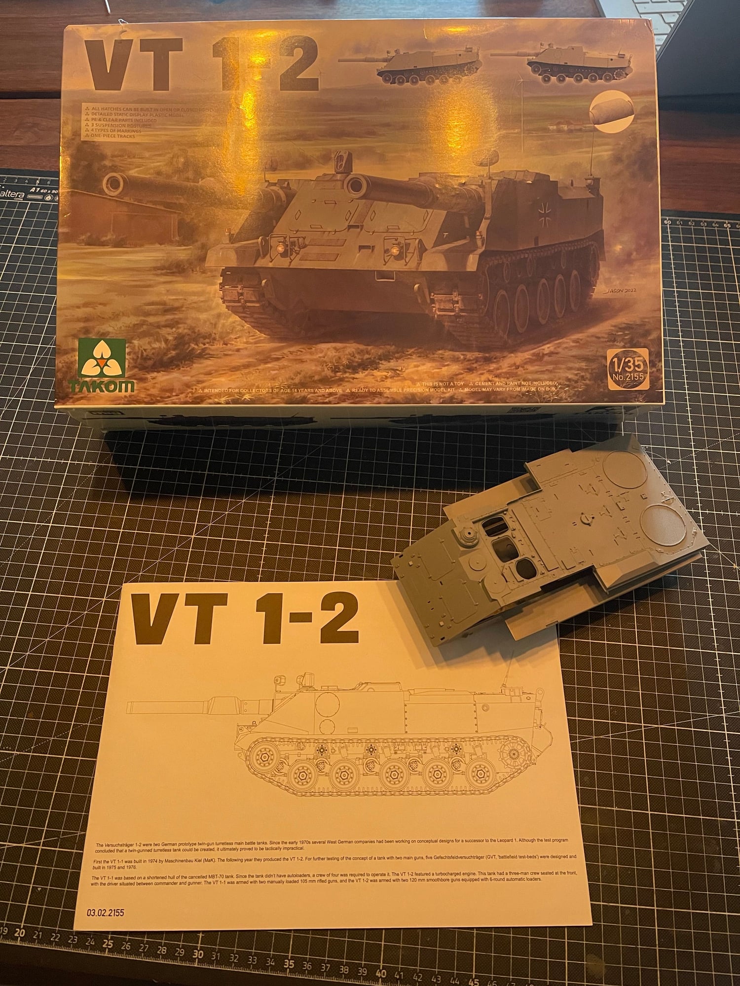
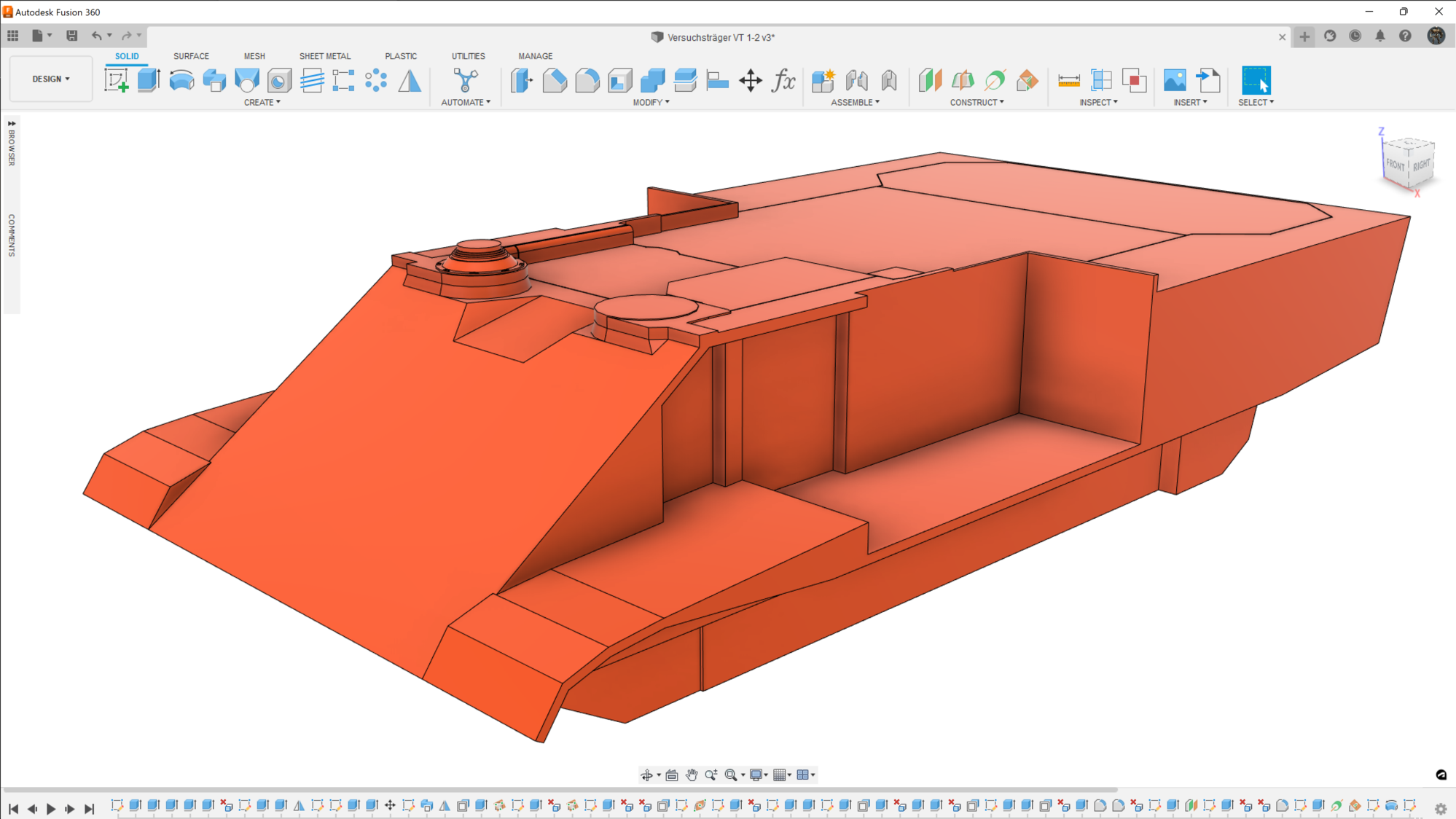
I've also already started blocking out the majority of the Hull to think about where to cut it up for easier 3D Printing before adding the details:
Which brings me to the Poll...
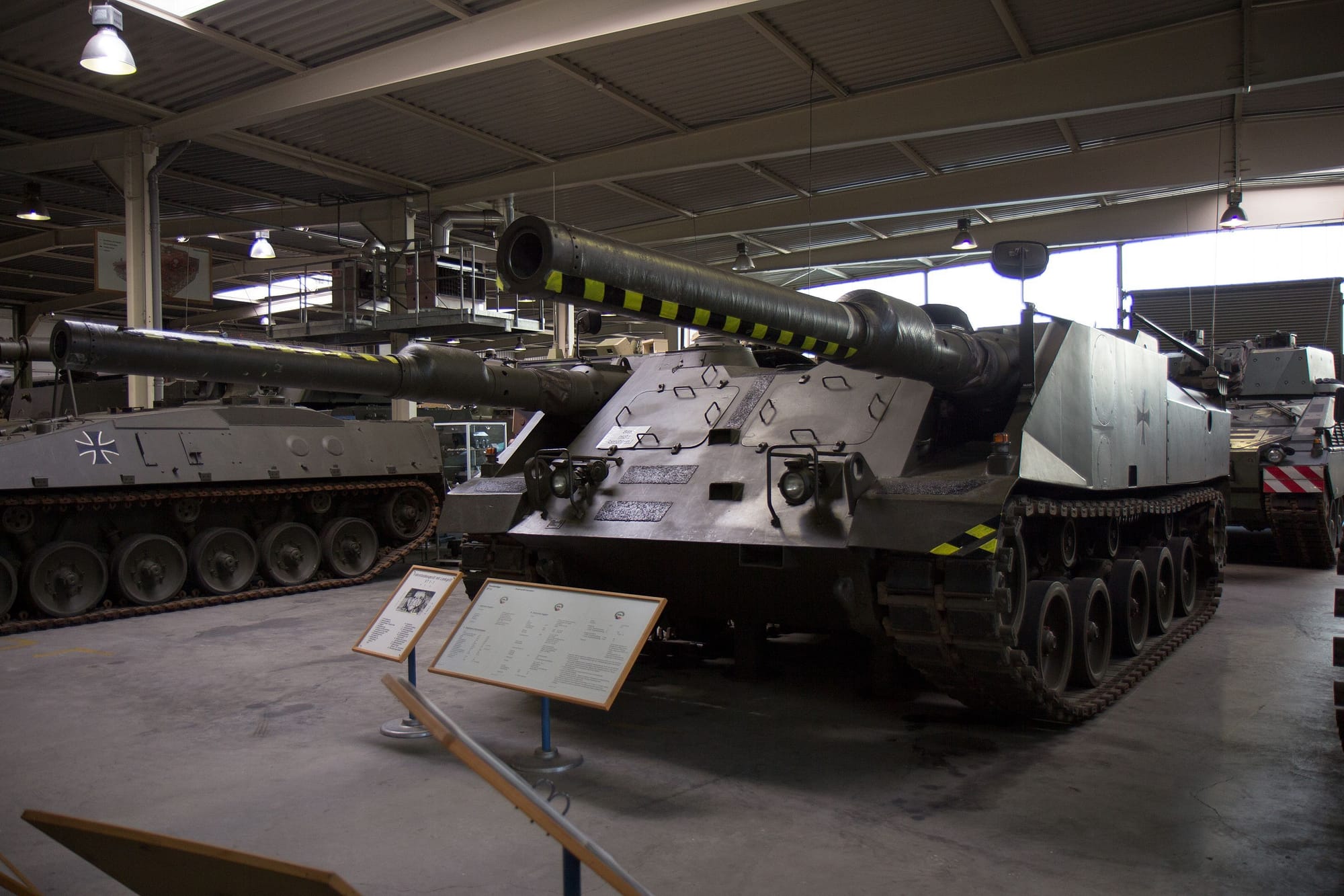
The full-scale Testbed Tank ( and subsequently also the 1:35 scale Model ) has these two huge hatches at the front which I assume were put in place for easy access to the crew in case of an emergency like it having toppled over during one of the evaluation test runs - which I guess makes sense - but I can't really imagine them outfitting the actual Combat Vehicle with such a glaring weak spot like a door where it would most likely be hit so yea... Opinions on omitting those?
The Versuchsträger VT 1-2:
Like with my E-100 a 1:35 Scale Model will be used as a reference for picking up the Dimensions - In this case the recently released TAKOM #2155 VT 1-2:
I've also already started blocking out the majority of the Hull to think about where to cut it up for easier 3D Printing before adding the details:
Which brings me to the Poll...
The full-scale Testbed Tank ( and subsequently also the 1:35 scale Model ) has these two huge hatches at the front which I assume were put in place for easy access to the crew in case of an emergency like it having toppled over during one of the evaluation test runs - which I guess makes sense - but I can't really imagine them outfitting the actual Combat Vehicle with such a glaring weak spot like a door where it would most likely be hit so yea... Opinions on omitting those?
 08-26-2022, 05:19 PM
#2
Did you find any references to their use as crew escape hatches? To me they look like maintenance hatches. I can't speak to modern German tank destroyer doctrine as the US abandoned tank destroyers after WW2. The tank could've been designed to fire from dug in, fixed locations where they weren't expected to fight tanks head on. It's really hard to say.
08-27-2022, 03:36 AM
#3
Thread Starter
I don't have any evidence them being crew hatches but considering the status of that particular vehicle as a testbed it is pretty much the only thing that makes even just remotely sense to me...
I guess I'll have to write the museum a letter requesting for clarification 🤔
I guess I'll have to write the museum a letter requesting for clarification 🤔
08-27-2022, 11:43 AM
#4
My Feedback: (1)
Join Date: May 2009
Location: Pearl City, HI
Posts: 372
Likes: 0
Received 0 Likes
on
0 Posts
Looking at the museum photo, you can see that there are several bolted-on hold-down blocks for those hatches. Those probably wouldn't have been able to be removed from the inside, and especially not quickly in an emergency. I'd vote for infrequently opened maintenance hatches.
09-04-2022, 05:30 PM
#5
Thread Starter
Had a bit of a lazy week so not much done except for actually dipping my toes into casting some metal parts for E-100 which went kinda south as I immediately burned my Silicone Mould to a crisp? 🤔
I guess reading up on casting Pewter but then actually pouring ZAMAK into the mould at a 150°C elevated temperature is causing some side effects. Classic me...🤣
Tried contacting the Museum via eMail concerning the matter of the two Hatches at the front but no luck... I guess everyone's on vacation ( mild cursing 😑 )
Since I'm going with a combat vehicle, I'll be leaving them out as they just don't make any sense to me for anything other than either a more convenient parts exchange or assisted crew evacuation during the testing phase of the vehicle.
Anyway... Did some more work on the VT 1-2 and did most of the Detail Parts of that is parts of and around the Running Gear...
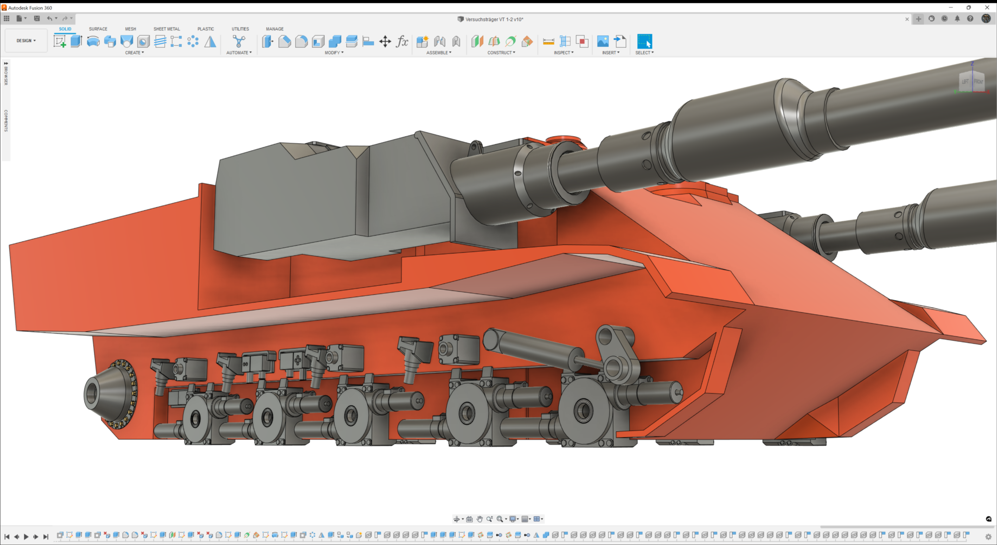
Assemblies like the Idler Wheel Tensioner with its Shock Absorber were left in a rough shape until I've made Progress with other parts like the Wheels and Drive Sprockets first 😩
I guess reading up on casting Pewter but then actually pouring ZAMAK into the mould at a 150°C elevated temperature is causing some side effects. Classic me...🤣
Tried contacting the Museum via eMail concerning the matter of the two Hatches at the front but no luck... I guess everyone's on vacation ( mild cursing 😑 )
Since I'm going with a combat vehicle, I'll be leaving them out as they just don't make any sense to me for anything other than either a more convenient parts exchange or assisted crew evacuation during the testing phase of the vehicle.
Anyway... Did some more work on the VT 1-2 and did most of the Detail Parts of that is parts of and around the Running Gear...
Assemblies like the Idler Wheel Tensioner with its Shock Absorber were left in a rough shape until I've made Progress with other parts like the Wheels and Drive Sprockets first 😩
The following users liked this post:
tankme (09-04-2022)
02-16-2023, 07:41 AM
#6
Thread Starter
Had some CAD Updates happening regarding the Running Gear and Differential Gearbox of my VT 1-2:

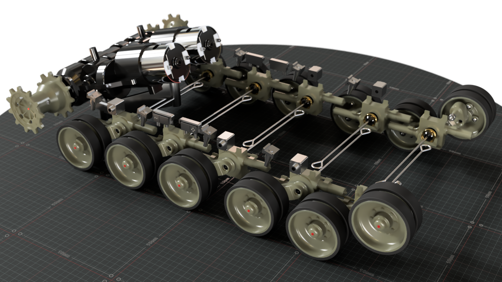
An older Image of the Leopard 2A6 Roadwheels / Idler Wheels attached to the Model and a placeholder Final Drive Support Cone at the back.

20° Angled Differential Gearbox ( with Final Drives and Drive Sprockets attached ) to make room underneath it for the Motorized Suspension System.

Unfortunately the Track Width on the VT 1-2 appears to be wider in total than that of the Leopard 2A6 and as such a 6mm Extension on each side at some location will be necessary with the only realistic place for that being an elongated Nut the Drive Sprocket mounts to.
An older Image of the Leopard 2A6 Roadwheels / Idler Wheels attached to the Model and a placeholder Final Drive Support Cone at the back.
20° Angled Differential Gearbox ( with Final Drives and Drive Sprockets attached ) to make room underneath it for the Motorized Suspension System.
Unfortunately the Track Width on the VT 1-2 appears to be wider in total than that of the Leopard 2A6 and as such a 6mm Extension on each side at some location will be necessary with the only realistic place for that being an elongated Nut the Drive Sprocket mounts to.
 02-16-2023, 05:12 PM
#8
Interesting, basically a TD with no gun lateral movement. The description of the intended tactical use is interesting at best:
"The idea was that the tank would close in on the enemy on a zig-zag course (Wedelfahrt, much like a skier wedeling downhill), which would make it much harder for the enemy to aim. The target would be locked into the aiming computer, the gunner would hold the trigger and the gun would fire automatically in the moment when the muzzle was on the target during the next change of direction." -Wikipedia
This would make for a difficult tank to use in IR battles for sure.
02-16-2023, 06:04 PM
#9
Jimmy
02-17-2023, 06:02 PM
#10
Thread Starter
It would most definitely need a custom board allowing for two IR Shots to be fired in quick succession otherwise it would only reap in the negatives of having no Turret.
Unless something changes in the market by the time I get to installing the Electronics I'll mostly be going with a Beier SFR-1-D that found good use in my E-100.
It sports enough Outputs for at least operating the Mechanical Components:
- 2x Servos for the two Cannon Recoils ( programmed for them to be fired ever so slightly staggered )
- 1x Servo for lowering and raising both Cannons simultaneously
- 1x Servo for tilting the Tank up and down
- 2x 540 Motors for the Drive System
- 1x Micro Motor for a turn able Periscope
- 1x Micro Motor for a Bulldozer Blade ( just an idea... )
02-20-2023, 11:36 AM
#11
Thread Starter
Finally spent some quality time on my CNC giving milling Aluminium a try... Should have started doing that much sooner as it turned out to be a lot less of an issue than anticipated ( no gummed up or broken Endmills ) 🤔
It did take me three attempts but at last I managed to get a pair of dimensionally accurate Adapters out of it despite hogging more material away than I'm now presenting on my table 😭:
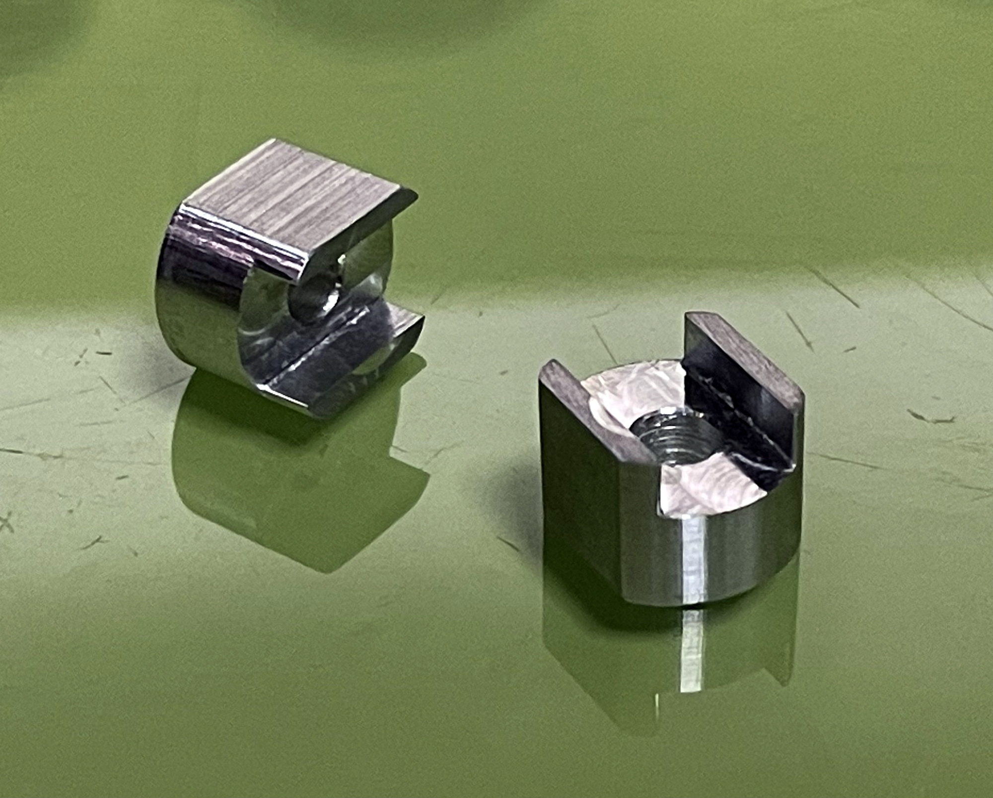
They're still missing the M3 threaded Holes for the Screws securing the Drive Sprockets to the Adapters but those shouldn't be an issue 😅
With that hurdle out of the way I'd say it suddenly makes a whole lot more sense progressing with the purchase of the Gearbox Parts 😁
It did take me three attempts but at last I managed to get a pair of dimensionally accurate Adapters out of it despite hogging more material away than I'm now presenting on my table 😭:
They're still missing the M3 threaded Holes for the Screws securing the Drive Sprockets to the Adapters but those shouldn't be an issue 😅
With that hurdle out of the way I'd say it suddenly makes a whole lot more sense progressing with the purchase of the Gearbox Parts 😁
02-24-2023, 06:31 PM
#12
Thread Starter
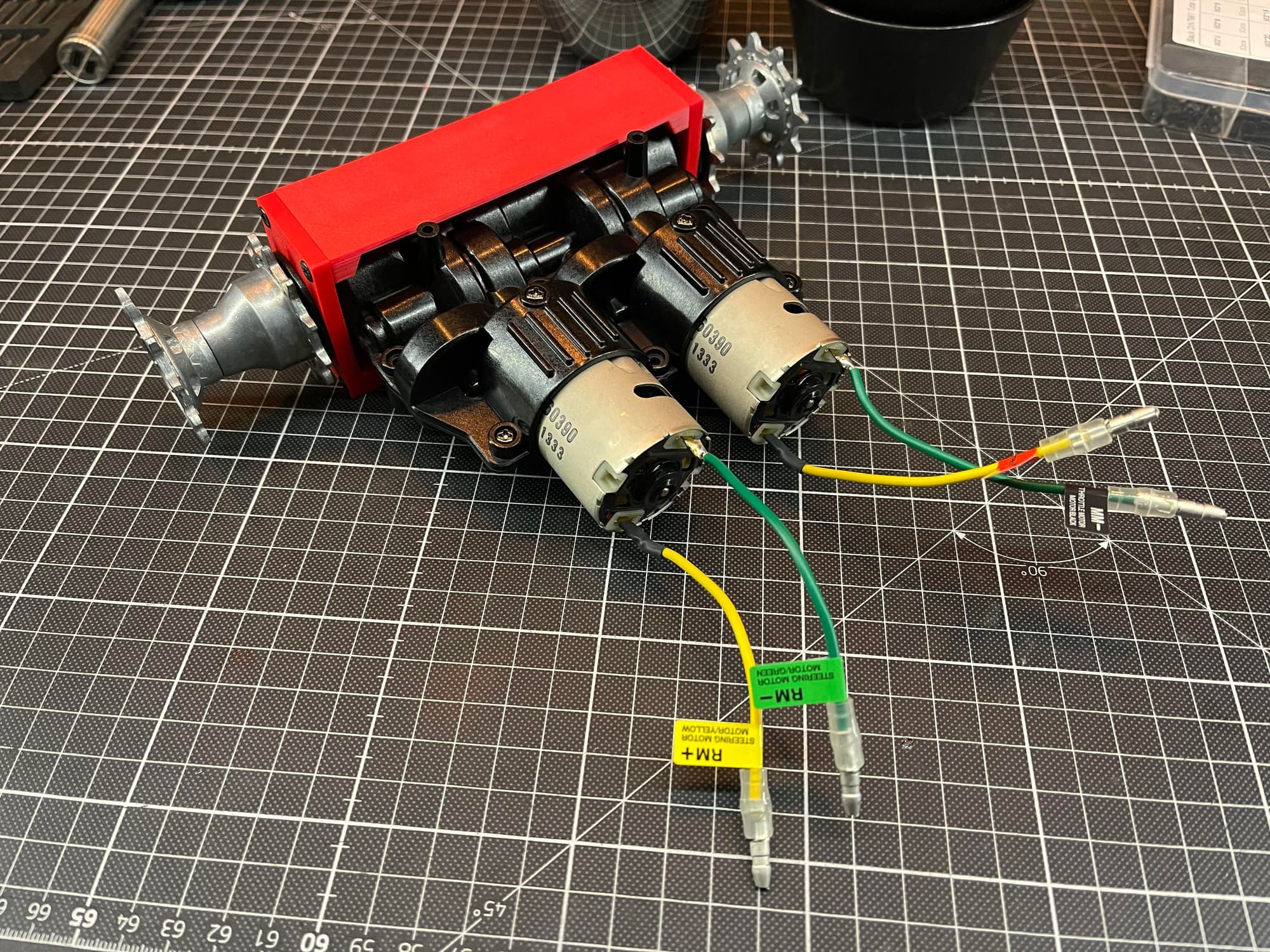
Differential Gearbox has arrived and was assembled in its stock configuration - The red Box acts as a temporary Hull to prevent the Final Drives from detaching...
Spent some more time Brainstorming on the Suspension which is going to be a tough Nut to crack if I want it to be an Active Suspension 😑
Turns out bending the Ends of the Torsion Bars upwards to gain some real estate between them and the Floor for the Mechanism to fit all around is not gonna happen as there's like zero Vertical Play between the Torsion Bar and the Bearing Cylinder they slide into.
So, whatever the Mechanism will look like will have to make do with being confided to the space above the Torsion Bar still having its Axis of Rotation aligned along the natural Twist Axis of the Torsion Bar and while I do already have an idea how to approach that it sure is going to be a R.P.I.T.A. to pull off 😵 At least I got my newfound Aluminium Milling Skills that may be of help if 3D Printing won't cut it 🤣
In any case "I'm gonna have to science the 💩 out of this" 😁
06-23-2024, 04:01 PM
#13


