


New Tamiya Ta05 ver 2 - #58466
 02-20-2011, 09:32 PM
#26
Junior Member
Thread Starter
Join Date: Feb 2011
Location: Washington, DC
Posts: 14
Likes: 0
Received 0 Likes
on
0 Posts
Whoa.. calm down there captain. Not turning turnbuckles while they're on the car....atleast not with pliers.
No, I was talking to the 1st step, of screwing on the plastic rod ends onto the metal rod doohickey.. you know how you make a turn buckle in the first place.
I will post pics, once i get em off the camera. Seem to have lost the usb connector.
Picked up a mamba max Pro with a 6900KV motor from the LHS. I did try mounting it in but it seems like a tight fit - the ESC that is.
 02-20-2011, 09:55 PM
#27
Senior Member
Join Date: Jun 2010
Location: Sequim,
WA
Posts: 888
Likes: 0
Received 0 Likes
on
0 Posts
Yah, The MMP/Sidewinders have a fairly large footprint (more so the sidewinders).
I try to clean up the wiring by shortening the motor leads either at the ESC or motor, whichever will do the best job. Makes the power transfer more efficient, too.
I try to clean up the wiring by shortening the motor leads either at the ESC or motor, whichever will do the best job. Makes the power transfer more efficient, too.
02-22-2011, 04:43 PM
#28
Junior Member
Thread Starter
Join Date: Feb 2011
Location: Washington, DC
Posts: 14
Likes: 0
Received 0 Likes
on
0 Posts
Update:
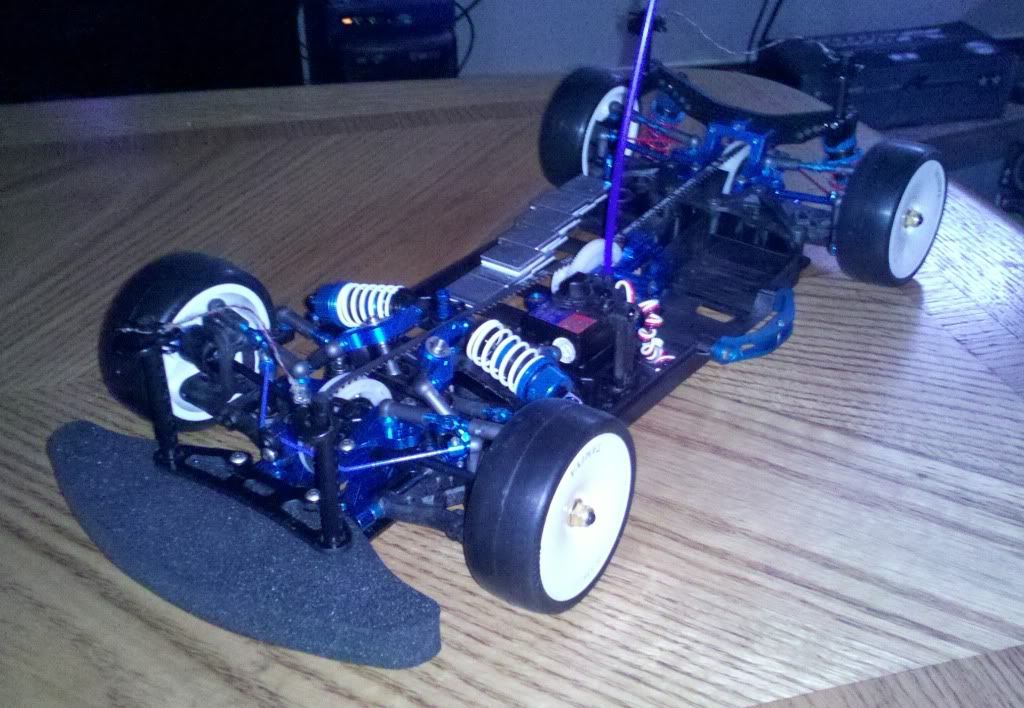
Who ever said the Mamba Monster Pro is a drop in fit for the Ta05 V2 chassis needs to get their eyes checked, or needs to re-evaluate the meaning of "drop-in fit "
The MMP will NOT fit unless there is some amount of material taken off the chassis. Just wanted to warn future buyers.
Here are some pictures of the offending ESC

</p>
02-22-2011, 06:40 PM
#30
Senior Member
Join Date: Jun 2010
Location: Sequim,
WA
Posts: 888
Likes: 0
Received 0 Likes
on
0 Posts
Just to let you know (and I'm glad I'm not the one who told you it would be a drop-in fit), you can mount the ESC sideways or on one of it's ends, if it won't fit flat. There is no one way an ESC can be mounted. It doesn't have to be mounted flat, right side up.
Though the job you did is clean! Yah, you had to remove material, but it won't affect anything adversely. Look at it this way, if and when you go carbon, the MMP will fit the carbon plate MUCHeasier!
Looking great, by the way!
Though the job you did is clean! Yah, you had to remove material, but it won't affect anything adversely. Look at it this way, if and when you go carbon, the MMP will fit the carbon plate MUCHeasier!
Looking great, by the way!
02-22-2011, 09:31 PM
#31
Junior Member
Thread Starter
Join Date: Feb 2011
Location: Washington, DC
Posts: 14
Likes: 0
Received 0 Likes
on
0 Posts
hmm,
I think I might have to create a mount for the esc and double side tape it in.
the ESC needs to be raised a bit to get access to the sensor port.
I think I might have to create a mount for the esc and double side tape it in.
the ESC needs to be raised a bit to get access to the sensor port.
02-22-2011, 10:58 PM
#32
Senior Member
Join Date: Jun 2010
Location: Sequim,
WA
Posts: 888
Likes: 0
Received 0 Likes
on
0 Posts
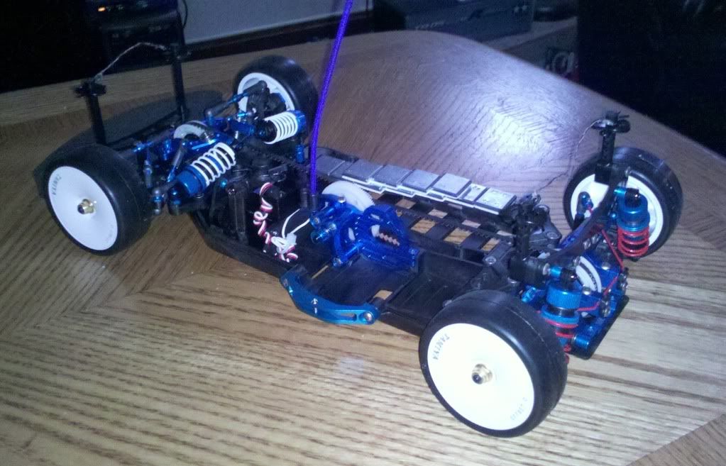
Well, you want to keep weight as low as possible, and you can position the ESC so you have easy access to the sensor port without raising it up. Might look strange, but at least the weight is low, which is always a good idea.
Might want to give the motor wires a trim, as I'm seeing a lot of wiring sticking up, there. Up to you.
It's getting there!
Might want to give the motor wires a trim, as I'm seeing a lot of wiring sticking up, there. Up to you.
It's getting there!
02-24-2011, 12:11 PM
#33
Senior Member

Join Date: Feb 2009
Location: Oakland,
CA
Posts: 2,233
Likes: 0
Received 0 Likes
on
0 Posts
I never use an Xacto knife to cut the parts off the tree as it requires too much effort sometimes. Instead I use small wire cutters just make sure they are a good brand or else your cut offs won't be clean at the edges. Just a suggestion for your next build.
02-25-2011, 03:01 PM
#34
Banned
Join Date: Sep 2010
Location: Northampton,
MA
Posts: 1,766
Likes: 0
Received 0 Likes
on
0 Posts
I never said that it would be a drop-in fit for the MMP ESC. I can understand your frustration though.
I did do my research and measured the ESC area on the lower deck. The numbers show that it will be a snug fit, and will only fit it two ways.
Also, I don't use the sensor port, as the MMP is designed to run any BLmotor sensored or sensorless. Even at the track I get away with it b/c of no limit on the ESC rules there.
So I may have suggested something that is a tight fit, but I find that ESC bulletproof against any battery or motor setup I choose. I had to mill out the lower deck on my TA05-R to get my 1st MMP to fit, and even there, I couldn't use a sensored cable even if I tried b/c it's even a tighter fit.
If you do like the MMP and want to keep it and use it in your car, I'd suggest milling the walls to half their thickness with a de-burring bit and a rotary tool. This should give you a couple of mm more and enable you to snake in the sensored port cable. It may have to be plugged in before the ESC is installed.
Again, I also apologize for the turnbuckle debacle.
Here's what I do to make turnbuckles en mass, quick and easy:
I use a dremel tool with a drill bit chuck adapter and a vise. I seat the plastic ball cup in the vise, and fit the turnbuckle into the drill chuck, and then use a low speed to screw it into the ballcup end. Flip the half-assembled turnbuckle. One end done!
I couldn't use the dremel for the other end, since the ballcup is now attached, so the longest part was the second end. I seated another ballcup end into the vise and just cranked the turnbuckle with its tool until I got it done.
I wish I could've use the dremel for both ends, but it still cut assembly time in half, and is a much better alternative than putting every one of em together one at a time by hand.
Substitute the vise with pliers if you don't have access to one. A variable speed drill with reverse is also a sub for a dremel, but bulkier and I imagine a little more awkward to use. If you do use pliers instead of a vise in the future, be careful
Whether or not this is now old news to you, I want you to know that I said the ESC should fit, and never ever said in this thread that it is a drop-in fit.
 04-05-2011, 09:43 AM
#36
Junior Member
Thread Starter
Join Date: Feb 2011
Location: Washington, DC
Posts: 14
Likes: 0
Received 0 Likes
on
0 Posts
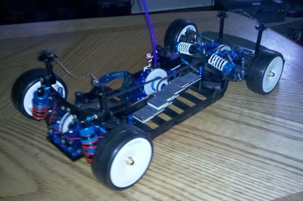
nice pics dragnse7en.
I see you still don't have an ESC in there.
Anyways, I'm done building the car and painting the body. Still need to do some adjustments to the camber,slop,toe-in,steering.. lol.
wow - didn't think building a toy car could get so complicated.<br type="_moz"/>
I see you still don't have an ESC in there.
Anyways, I'm done building the car and painting the body. Still need to do some adjustments to the camber,slop,toe-in,steering.. lol.
wow - didn't think building a toy car could get so complicated.<br type="_moz"/>
04-05-2011, 10:04 AM
#37
Banned
Join Date: Sep 2010
Location: Northampton,
MA
Posts: 1,766
Likes: 0
Received 0 Likes
on
0 Posts
ORIGINAL: nev_neo
nice pics dragnse7en.
I see you still don't have an ESC in there.
Anyways, I'm done building the car and painting the body. Still need to do some adjustments to the camber,slop,toe-in,steering.. lol.
wow - didn't think building a toy car could get so complicated.
nice pics dragnse7en.
I see you still don't have an ESC in there.
Anyways, I'm done building the car and painting the body. Still need to do some adjustments to the camber,slop,toe-in,steering.. lol.
wow - didn't think building a toy car could get so complicated.
Yeah I'm moving so I haven't been able to spend anything on that car in some time. What are you doing about your MMP? I will mill out my chassis with my dremel to get any room I need; I have no intentions of entering this ride in a TCS race. I had to do the same thing for my TA05-R. There's a litlle more room on my ver.II chassis, so I can see that I don't have to cut out away as much.
04-10-2011, 09:11 AM
#38
Senior Member
My Feedback: (2)
Join Date: Dec 2007
Location: Orlando, FL
Posts: 872
Likes: 0
Received 0 Likes
on
0 Posts
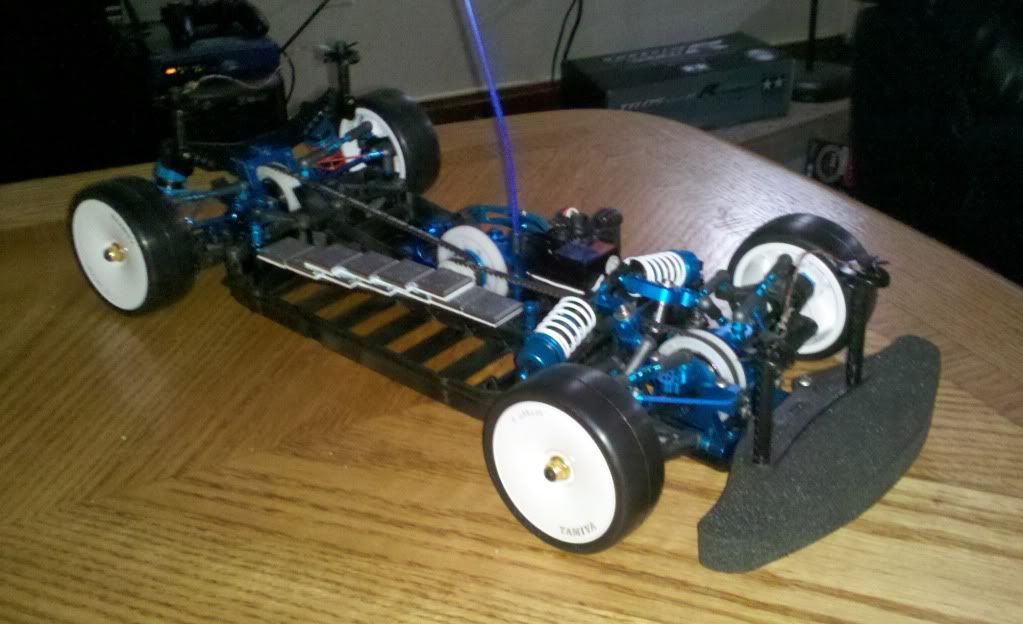
Finished this build a week or two ago..
MG servo
Futaba Megatech 2PL FM
Tamiya 10.5 BL system (sensored)
Tamiya threaded aluminum shocks
4200 2s LiPo with alarm

I have godly amounts of torque and I think I'm undergeared, I think I'm running around 25-30 mph. I've upped the pinion from 20 to 26. Is this suitable? The temps were only warm on the motor using the 20 pinion. Or is the 10.5 just slow and I'm too used to the mamba 7700?
MG servo
Futaba Megatech 2PL FM
Tamiya 10.5 BL system (sensored)
Tamiya threaded aluminum shocks
4200 2s LiPo with alarm
I have godly amounts of torque and I think I'm undergeared, I think I'm running around 25-30 mph. I've upped the pinion from 20 to 26. Is this suitable? The temps were only warm on the motor using the 20 pinion. Or is the 10.5 just slow and I'm too used to the mamba 7700?
04-10-2011, 01:11 PM
#39
Banned
Join Date: Sep 2010
Location: Northampton,
MA
Posts: 1,766
Likes: 0
Received 0 Likes
on
0 Posts
I get a little more power by not using the sensor harness. I just needed to be sure that I connected the motor wires in the matching color order. The motor cogs a little bit every once in a while, while my 7700Kv motor does it more. I can relate when you mentioned going down to a slower motor afterwards - look I have an r/c snail!!!!
I don't know if a 26 tooth pinion will fit using the 70 tooth spur gear. The chart in the instruction manual only goes up to 25 on the pinion, and I have run into problems in the past, trying to get a certain final drive ratio for indoor carpet races. One time the spur was too big to fit, and another combination would not allow the gears to even touch each other. You can probably get the right room to get the 26t pinion to mesh good if you get a 68t spur Tamiya item #51423. That would make your final drive ratio 5.37:1
I don't know if a 26 tooth pinion will fit using the 70 tooth spur gear. The chart in the instruction manual only goes up to 25 on the pinion, and I have run into problems in the past, trying to get a certain final drive ratio for indoor carpet races. One time the spur was too big to fit, and another combination would not allow the gears to even touch each other. You can probably get the right room to get the 26t pinion to mesh good if you get a 68t spur Tamiya item #51423. That would make your final drive ratio 5.37:1
04-10-2011, 07:54 PM
#40
Senior Member
My Feedback: (2)
Join Date: Dec 2007
Location: Orlando, FL
Posts: 872
Likes: 0
Received 0 Likes
on
0 Posts
Could you please explain the FDR to me? What FDR do I optimally want? What is the difference between a higher and lower one?
Thanks!
Thanks!
04-11-2011, 11:27 AM
#41
Banned
Join Date: Sep 2010
Location: Northampton,
MA
Posts: 1,766
Likes: 0
Received 0 Likes
on
0 Posts
ORIGINAL: aftermarket
Could you please explain the FDR to me? What FDR do I optimally want? What is the difference between a higher and lower one?
Thanks!
Could you please explain the FDR to me? What FDR do I optimally want? What is the difference between a higher and lower one?
Thanks!
FDRis the number of times a nitro engine or electric motor needs to turn to make the tires make a single revolution. This number is used for any rc vehicle, nitro, electric, offroad or on road, 2WD or 4WD. There is no relevance for gear pitches for the FDR formula, since it is using a measurement of ratios to scale against a single 360 degree revolution.
Different gear boxes and pitch size gears are turned by a common spur and pinion gear.
To get the Final Drive Ratio, you will need to know what the gear ratio of the car has. This is where I find out if the company makes a good car; if a gearing chart is included in the instruction manual. This shows that the company did some research and knows what gears will fit in the drivetrain. If you don't know what the gear ratio is, or cannot find it in the instruction manual, the calculation for solving that is easy. Count the number of teeth on the diff gear or diff pulley, and then count the number of teeth on the counter gear or center pulley.
The formula for calculating the gear ratio is as such:
Diff gear or diff pulley teeth = X
Counter gear or center pulley = Y
Gear Ratio = Z
X/Y = Z
An example; if I have a diff gear of 46 teeth and the counter gear has 18 teeth, then the formula shall be 46/18 = 2.56 (2.555555555). For practical purposes and ease of use for these two formulas, we will use the value of Z above for both.
The formula for calculating the Final Drive Ratio is as such:
Spur gear teeth = X
Pinion gear teeth = Y
Gear Ratio = Z (Gear Ratio shall be inserted here or copied from Z above)
X/Y * Z = FDR
Final Drive Ratios and Gear Ratios are usually expressed with a :1 at the end of the number, 4.75:1, 12.65:1, etc.
Offroad vehicles tend to lean to the higher FDR numbers for torque, traction, and good corning power. On road vehicles can typically use a wider range of numbers, but the numbers all mean the same; the higher the number, the more the motor or engine is cranking over to make the tires under power to revolve once.
In the late 1990s I used a ball park figure around the low nines and high eights for two electric stadium trucks I had, and have read in a Car Action mag that some of the short course trucks even use higher numbers, floating around the twelves. I run a wider range for my on road electric touring cars, from the mid sevens down to the high fours, depending on whether or not I'm parking lot bashing, indoor carpet race tracks, or insane speed runs.
The high fours I use are for my speed runs, and that ratio gets the esc and motor hot very quickly. The higher the FDR number the car is running, the slower and cooler it will run, and will have a lot of power and torque. The opposite goes for the low FDR numbers; less torque, more rpms but more friction, thus creating more heat.
Knowing how all this works is a valuable tool in the rc car hobby, and is mainly basic knowledge for avid racers everywhere. Another important note is to dial in the car's drivetrain that is both suitable for your driving style/ ability and a gear ratio suitable not to overheat the manufacturer's recommended temps for the motor and esc.
Hope this helps you decide what works for you - repost here and let us know what works the best!
04-11-2011, 01:40 PM
#42
Senior Member
My Feedback: (2)
Join Date: Dec 2007
Location: Orlando, FL
Posts: 872
Likes: 0
Received 0 Likes
on
0 Posts
Thank you very much for that informative information!
I'll go try several pinion/spur combos and get back to you guys. The stock gearing in my Version 2 had my 10.5 running lukewarm after 15 minutes, and it had serious torque. I feel that I should have gone with a lower turn motor, but hopefully I can get a few more mph out of the gearing without the motor demagnetizing.
Thanks again.
04-11-2011, 07:41 PM
#43
Banned
Join Date: Sep 2010
Location: Northampton,
MA
Posts: 1,766
Likes: 0
Received 0 Likes
on
0 Posts
ORIGINAL: aftermarket
Thank you very much for that informative information!
I'll go try several pinion/spur combos and get back to you guys. The stock gearing in my Version 2 had my 10.5 running lukewarm after 15 minutes, and it had serious torque. I feel that I should have gone with a lower turn motor, but hopefully I can get a few more mph out of the gearing without the motor demagnetizing.
Thanks again.
04-12-2011, 11:50 AM
#44
Senior Member
My Feedback: (2)
Join Date: Dec 2007
Location: Orlando, FL
Posts: 872
Likes: 0
Received 0 Likes
on
0 Posts
After looking through the motor manual, I found this chart:

Seems a bit high of a FDR for a tc, but I'll take it with a grain of salt and use this as a starting point. Moving up to a 21 tooth pinion will put me at 6.85, and moving up to a 22 pinion will put me at a FDR of 6.54. (Thanks for your great formulas!)
One or two teeth on the pinion probably won't give me the top end I'm seeking (probably impossible with the 10.5 anyway), but I'll get back to you after I try it out. I have a feeling the motor will run cool enough to allow a larger pinion gear.
04-13-2011, 01:23 PM
#45
Senior Member
My Feedback: (2)
Join Date: Dec 2007
Location: Orlando, FL
Posts: 872
Likes: 0
Received 0 Likes
on
0 Posts
Using a 22t pinion, I'm at a FDR of 6.54. Decent top end with a good dose of torque, and best of all, cool temperatures.
I'm not sure where to go from here, though. My lhs temporary track is only out the first weekend of each month, and they are really cutting down on practice days and the number of times they even put the track out anymore. The nearest permanent track is an hour away and is fenced off for races only.
This leaves me to try to create my own track to practice with, or take up drifting. Doesn't need a whole lot of wheel speed and space, and tracks are much easier to make.
04-13-2011, 01:48 PM
#46
Banned
Join Date: Sep 2010
Location: Northampton,
MA
Posts: 1,766
Likes: 0
Received 0 Likes
on
0 Posts
I would think Orlando would have plenty of on road tracks - enter a race for the fun!
Good to see you got a good starting point for the gearing as well.
Good to see you got a good starting point for the gearing as well.
05-01-2011, 03:43 PM
#47
Banned
Join Date: Sep 2010
Location: Northampton,
MA
Posts: 1,766
Likes: 0
Received 0 Likes
on
0 Posts
ORIGINAL: nev_neo
nice pics dragnse7en.
I see you still don't have an ESC in there.
Anyways, I'm done building the car and painting the body. Still need to do some adjustments to the camber,slop,toe-in,steering.. lol.
wow - didn't think building a toy car could get so complicated.
nice pics dragnse7en.
I see you still don't have an ESC in there.
Anyways, I'm done building the car and painting the body. Still need to do some adjustments to the camber,slop,toe-in,steering.. lol.
wow - didn't think building a toy car could get so complicated.
