


Help! CY models P-51 JP tailwheel retract set up
 03-28-2022, 04:13 PM
#1


Hi!
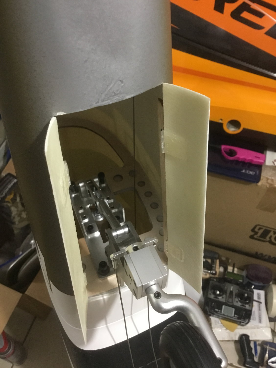
I need help from someone who has already assembled this! I’m in the process of assembling a CYmodels P-51 that includes the JP retracts and the new JP tailwheel retract. But for the life of me I can’t figure out how the steering is set-up, I know it should be a bit of a challenging set-up as the steering arm is below and outside the fuselage when the retract is down and the angles the steering cables would have would make it almost impossible to steer, so the should be some trickery to it (or maybe it’s very simple and I’m just a dummy)
The available manual is of no help at all as it is not updated to the new retract units
 03-28-2022, 04:17 PM
#2
Senior Member
Can you post pics cuz sonethin don't sound right...the steering horns for the pull pull should not be outside the fuselage on any retractable tail wheel. Something hinky.
 03-28-2022, 04:30 PM
#4
Senior Member
When its retracted, is the strut parallel with the gear doors or pointed towards top of fuselage? I'm assuming it swings about 90 degrees. In which case, its too low and needs to be moved up in the fuselage until the steering arm is a straight shot to the tubes extended. I don't think the JP was the origional meant to install there from the looks. You might have to do up some ply rails for it to bolt to to get it positioned right.
Depending on the angle of the wires, you could end up with some serious bind in the steering. If I were to hazard a guess, about 3/8s inch. But before you do, retract it, and manually close the doors with the wheel on..I'm guessing the wheel is going to make contact and doors won't fully close. They'll probably be stopped by the wheel before then.
Since the airframe has been out for a bit on the market and the tail retract is new, bound to need some structure to make it just so in the tail.
Take some 1/8th ply, cut to shape of retract wirh a 1/16th extra at every edge (for now) double it up so you got 1/4 inch thick. Laminate that with a good epoxy or hysol, once dry, mount the retract to that..then, you can see how all that needs to go in the fuselage and where to hysol it in. Mark the edges, then you can lighten your ply mount some.
You can sandwich new blind nuts between the block and the former to make it much easier to install and remove From there its get it where its going to function.
It will look better, function better, and the doors will function correctly as well..
But, yeah, its just too low on the former, in my opinion...but fixable fairly easily.
Last edited by Txmustangflyer; 03-28-2022 at 04:44 PM.
03-28-2022, 05:20 PM
#5
As I understand it, there has to be some other links added to make it work, there are some extra pieces, two that look like bell cranks ( 90 degree angle) but no instructions as to how to set it up, that’s why I need help from someone who has already done this, I just cant figure it out.
It cannot be installed higher in the fuse, the radiator intake will touch the ground
It cannot be installed higher in the fuse, the radiator intake will touch the ground
Last edited by Ruizmilton; 03-28-2022 at 05:24 PM.
03-28-2022, 05:26 PM
#6
Senior Member
Ok..so..that helps. The bell cranks would cone off the pull pull wires from the servo, a
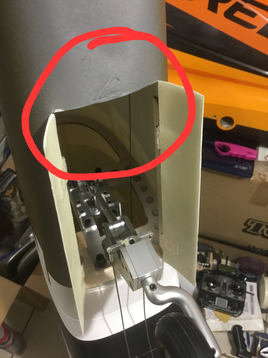
Look in this area for your turnbuckle mount holes.
second lead or linkage would then go to the steering arm...so in the bay, opposite where the retract mounts, you should have the tubes for the pull pull cables, then there should also be mounting holes for the turn buckles. Post a pic of the opposite end of the tail wheel bay from what you posted above.
The turnbuckle mounting ahould let the links from the turnbuckles to the steering arm go lax when retracted so its not pivoting in the bay and getting jammed up.
Last edited by Txmustangflyer; 03-28-2022 at 05:33 PM.
03-28-2022, 05:32 PM
#7
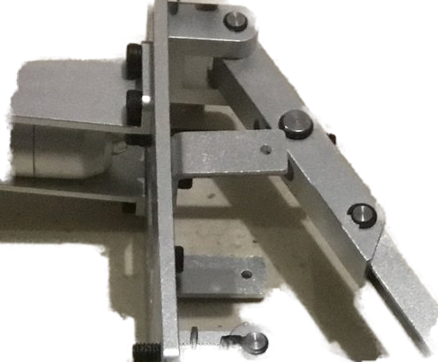
Pictured are all the parts included, I would know how to do it with 4 bellcranks, but not two, it also has centering springs, the possible attachment points are not on the available locations, the cables are just put in the arm for testing, they are not clamped

03-28-2022, 05:39 PM
#8
Senior Member
Ok, the two metal arms with the small holes, thats where your springs hook on, and go to the doors. They put tension on the doirs to hold them closed, basically.
Last edited by Txmustangflyer; 03-28-2022 at 05:43 PM.
03-28-2022, 05:44 PM
#10
Senior Member
Ueah, they have to go on opposite former..or on fuselage sides near the opposite former.
Its not meant to just castor with the turnbuckles being tied to a servo to open the doors...?
H9 mustang setup is a bit different. But, ypu could be right on those arms..the idea of a turnbuckle is to "turn" a linear movement 90 degrees..
Its not meant to just castor with the turnbuckles being tied to a servo to open the doors...?
H9 mustang setup is a bit different. But, ypu could be right on those arms..the idea of a turnbuckle is to "turn" a linear movement 90 degrees..
Last edited by Txmustangflyer; 03-28-2022 at 05:48 PM.
09-08-2024, 02:51 PM
#15

My Feedback: (3)
Join Date: Mar 2003
Location: Roseville,
CA
Posts: 991
Likes: 0
Received 0 Likes
on
0 Posts
I am at this point in the build also are you still going at it or have you found any solutions. I was just going to use a large Rudder servo arm and do the Rudder throw cables on the outside of the arm and put the Tail wheel control cables on the inside of the Servo arm. Or use a completely seperate servo for both.
Do the Tail wheel doors have to work also - that would be extra install work. Putting in the Cowl with those steel corner mounts is tricky also. Everything else seems straight forward.
Do the Tail wheel doors have to work also - that would be extra install work. Putting in the Cowl with those steel corner mounts is tricky also. Everything else seems straight forward.
