


PC-21 from WIND RC questions


 12-09-2023, 01:38 AM
#28
 12-20-2023, 02:01 PM
#30

Thread Starter
The fuel tank appears to be glued in place. There is a small brass outlet fitting with 4mm fuel line attached. This fitting appears to be glued in place as attempt to unscrew doesn�t seem to work. The tank is not very translucent and transilluminating the fuel tank I do not see a fuel pickup line or clunk.
anyone with experience with their XXL JMB PC-21
anyone with experience with their XXL JMB PC-21
The following users liked this post:
Ian Burridge (12-29-2023)
12-22-2023, 09:16 AM
#33
Thread Starter
David, was there a technique to get thru the double sided tape on the fuel tank you can share. I have tried a little bit of heat followed by trying to slide a straight edge razor blade or thin piece of brass with sharpened edges thru where I I think the tape is but must admit, not making much progress
12-22-2023, 12:54 PM
#34
Thread Starter
I think I I�m having success now. Using goo gone to soak lower front area of tank. I don�t have it for yet but able to work a flat probe much further under the tank
12-29-2023, 08:41 AM
#35
Thread Starter
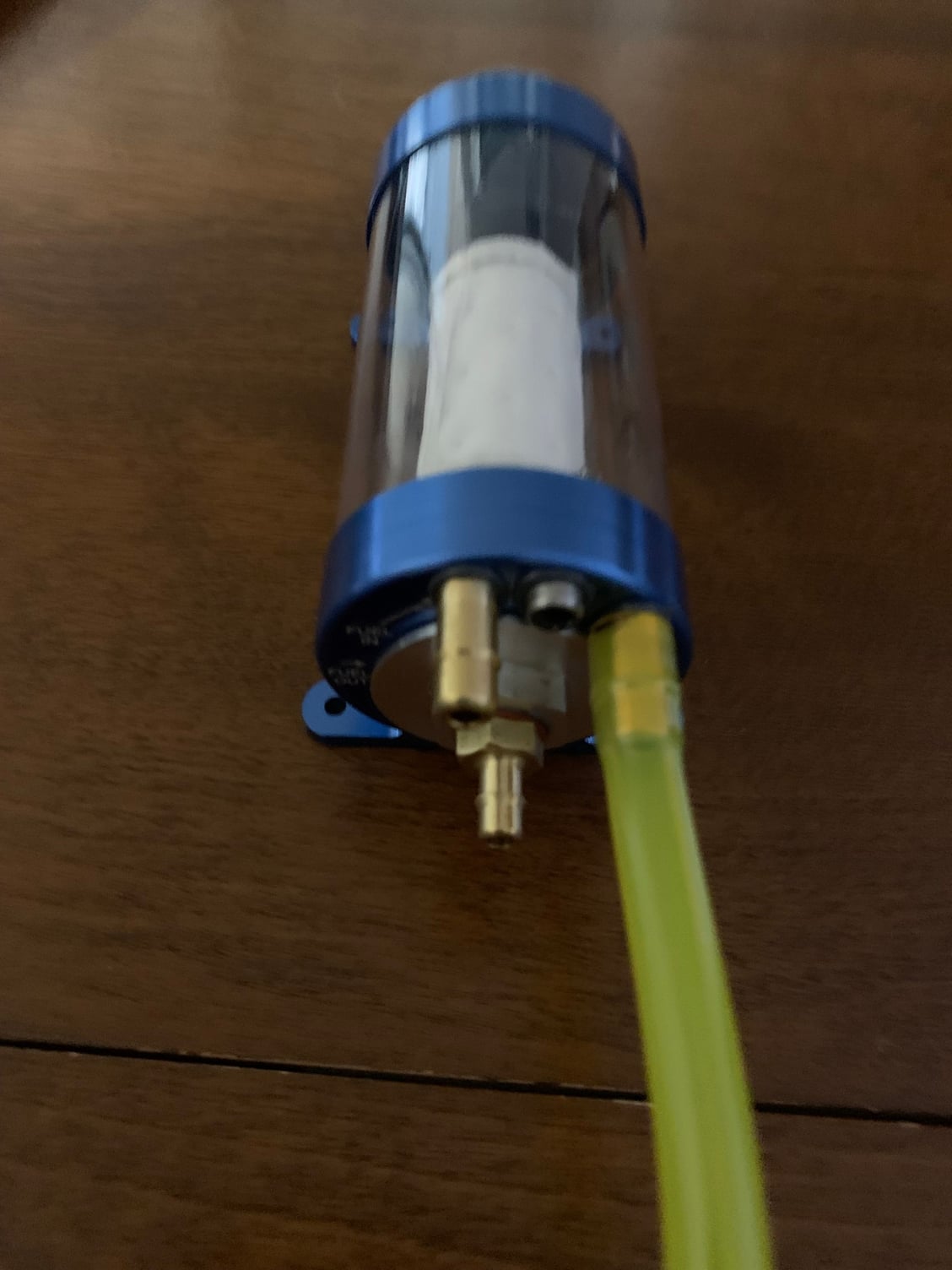
Replaced wind Rc fitting with jet tech fitting
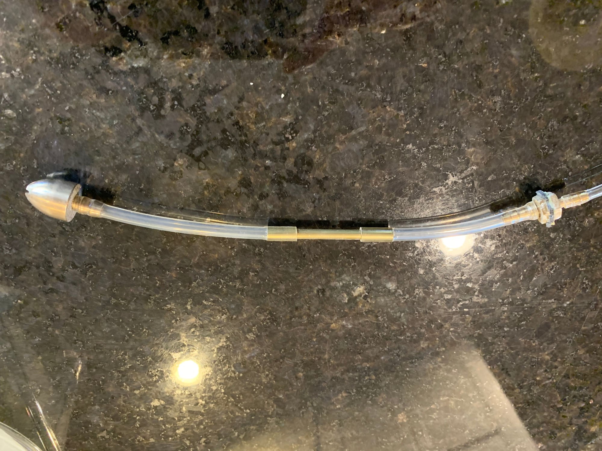
Stock internal plumbing. No safety wiring but very tight fittings that I don�t think would have come off. The brass tube really helps keep the clunk from flipping forward. The front tank fitting was glued in place and had to be dremeled out to fit the Jettech.
12-29-2023, 08:51 AM
#36
Thread Starter
I have not pressurized the fuel tank yet to look for leaks but will before re-installation. The tank was held in place with double sided sticky tape. They should sell the formula to 3M because it was densely adhered to the bottom of the fuel tank. Was difficult get the double-sided tape off the tank. In order to get it out of the plane I had to soak bottom of fuse that held the tank with �glu gone� and then slide a thin flat piece of brass underneath to separate. I�m pretty sure that tank wouldn�t be moving around in flight. I did check the fuel tank capacity and is exactly 3 liters. I will be placing a 1/16 foam sheet with adhesive just on one side on the bottom of the tank to give it slight cushion before it goes back in the plane. Still thinking about how I will secure the tank.
12-29-2023, 08:59 PM
#37
Thread Starter
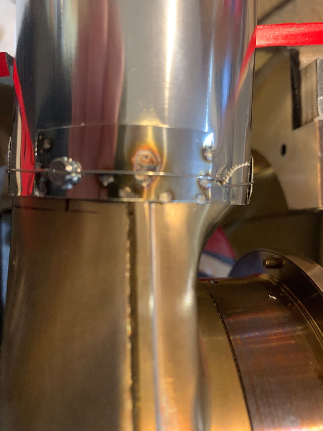
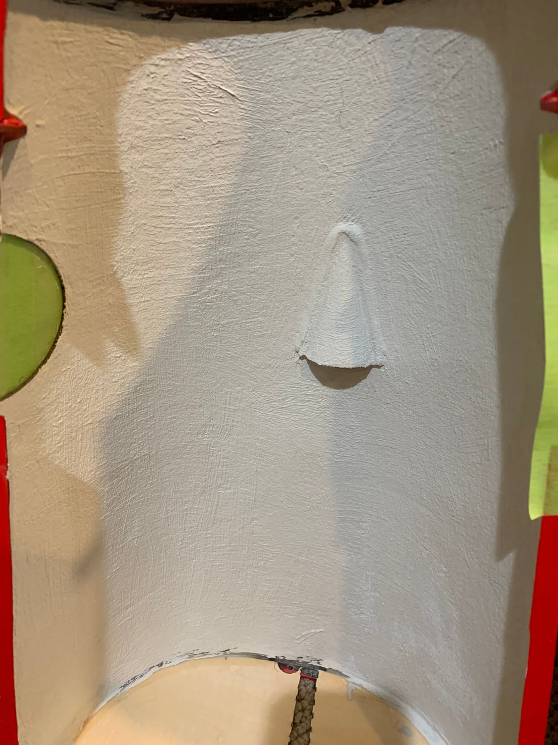
So pressure testing revealed a pin hole leak on the right side of the tank where the top half meets the lower half of the tank. There was a small dimple where the leak was coming thru the glued seam. A little E20HP and issue resolved
 01-16-2024, 07:53 AM
#42
Thread Starter
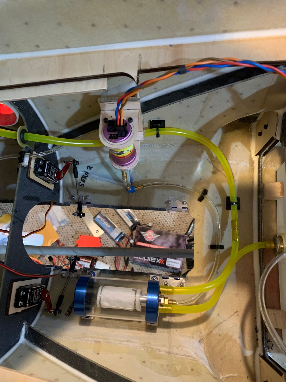
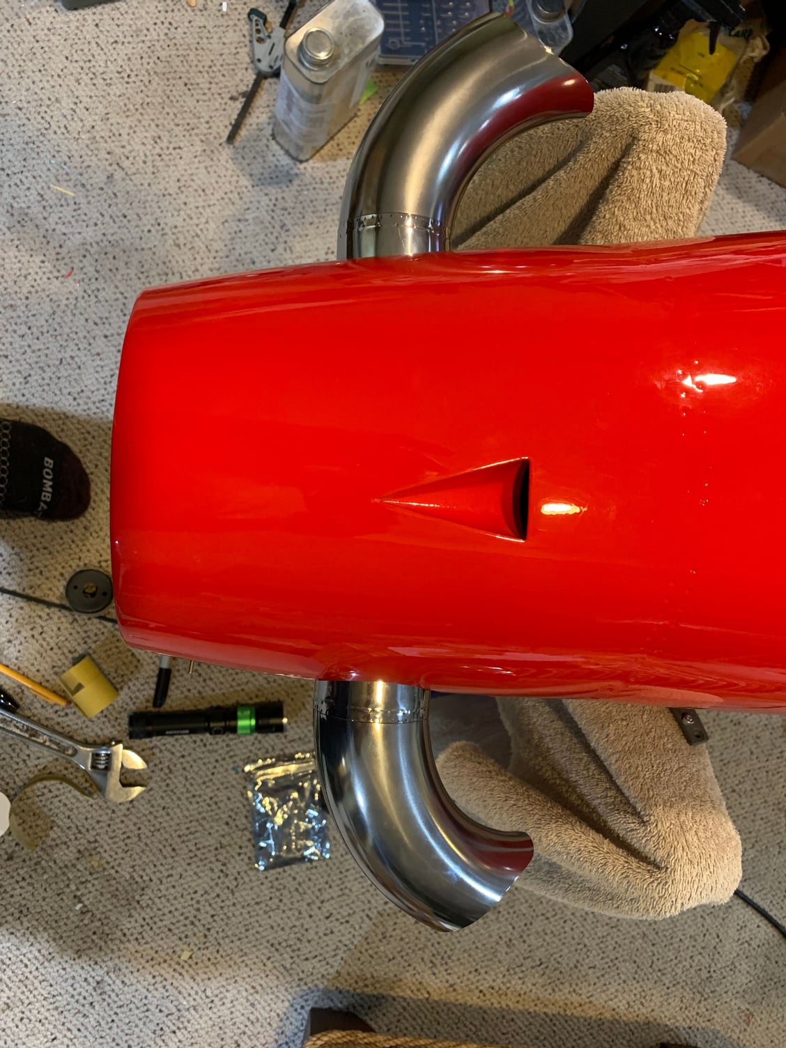
Fuel system plumbing almost done. Kept all this on fuse bottom with pump mounted vertically on the right side. Keeping everything ahead of CG. Still need to mount vent in bottom of fuse
 01-16-2024, 02:46 PM
#44
Junior Member
great job! recently put mine together with mods to make it the plane for more. i re enforced my fuel tank with cf along the seams. stock lights work. i have a upgraded light controller as well as upgraded gear controller. pm if you have questions.
01-17-2024, 05:19 PM
#46
Thread Starter
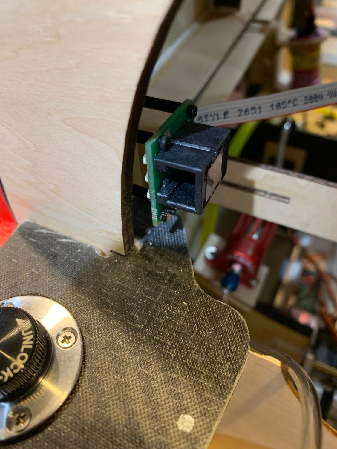
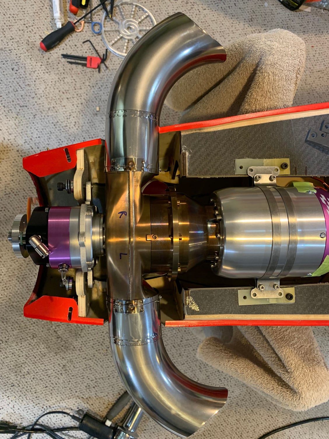
Jetcat I/O board mounted on a platform with a magnet. Then mounted just inside the right side behind a former that is immediately aft of turboprop hatch. Because of magnet release, very easy to pull out if needed or can leave in place for start up
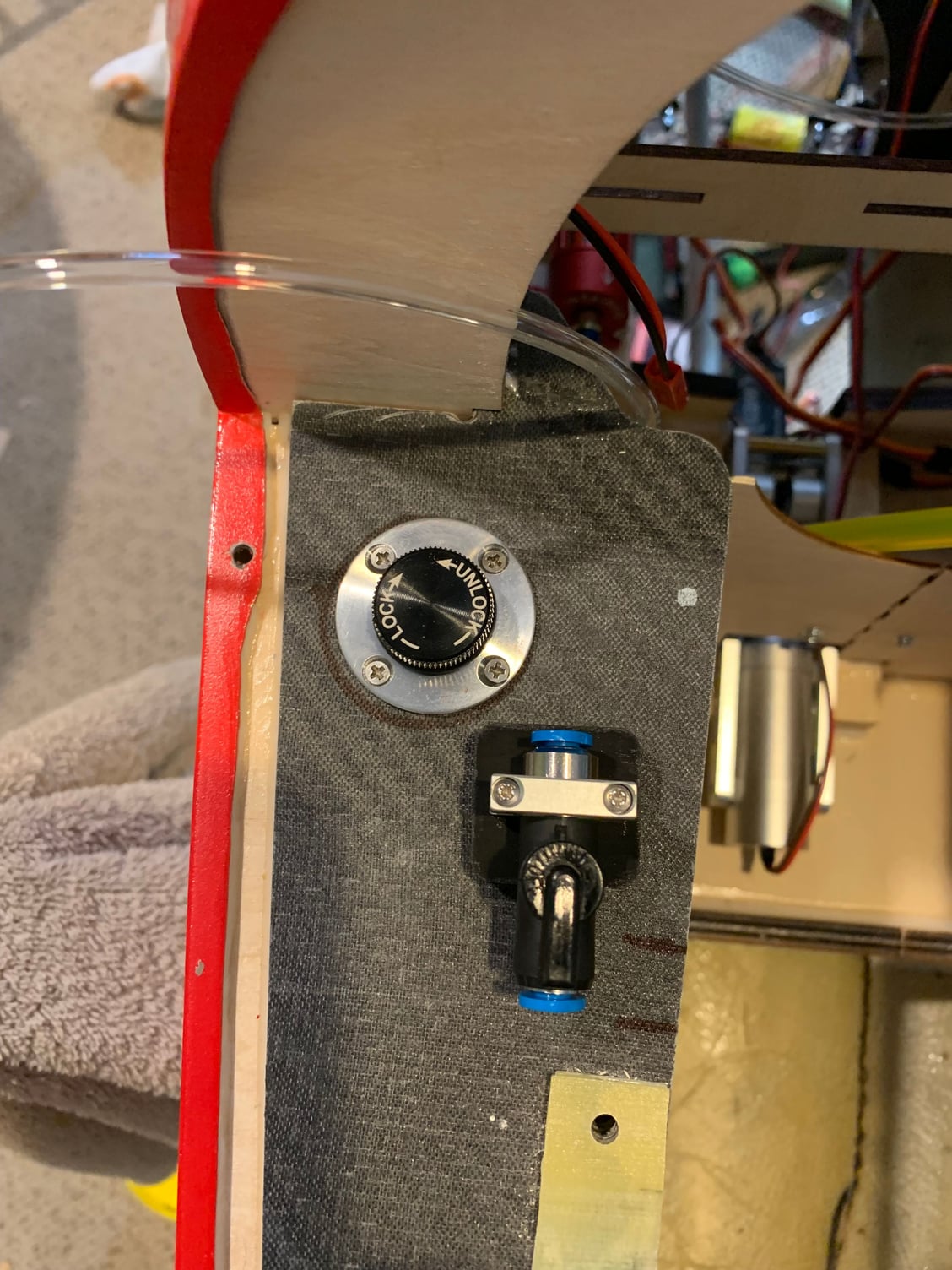
01-18-2024, 01:27 PM
#47
Thread Starter
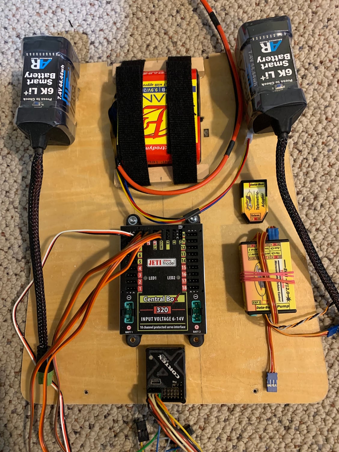
Electronic platform with receiver and ECU batteries forward. Jeti CB 320 with Demon Cortex Pro. Jetcat ECU and jetcat telemetry module. Will be installed on the reinforced platform mount in fuselage
01-28-2024, 11:11 AM
#50
Thread Starter
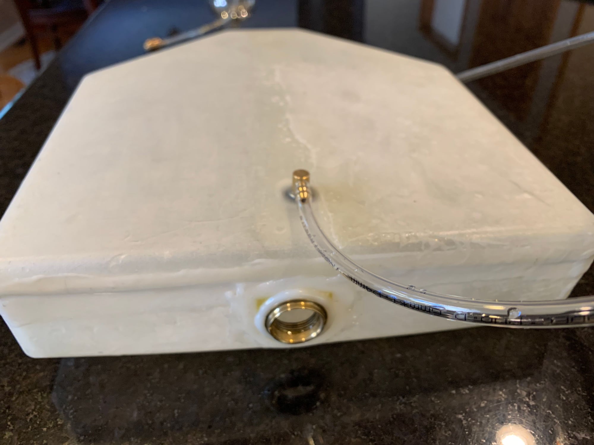
Thanks Westwind. I�ll think you�ll be pleased. The paint job on mine is really excellent. If not too late you may wish to ask wind Rc to wrap pilot seats in bubble wrap. They are glued into the bottom of the cockpit tub. When my kit arrived, both seats were floating around inside the tub and fuse is shipped on its side. As a consequence I have scratches on my rear canopy from the loose seat. I�m going to try and buff it out with Tamiya plastic model buffer. A few more pictures here. One is the vent tubing which bows up before going to vent mounted right behind nose wheel. The other picture shows tethered supports for the rear servo wires so no flopping around. Wires for lights are separate on fuse side. Plastic spiral wrap around some areas where cable ties are. The servo harnesses that came with my kit are plenty long. You could definitely put the power distribution box on the front of the plywood tray. I have all batteries up there to keep weight forward
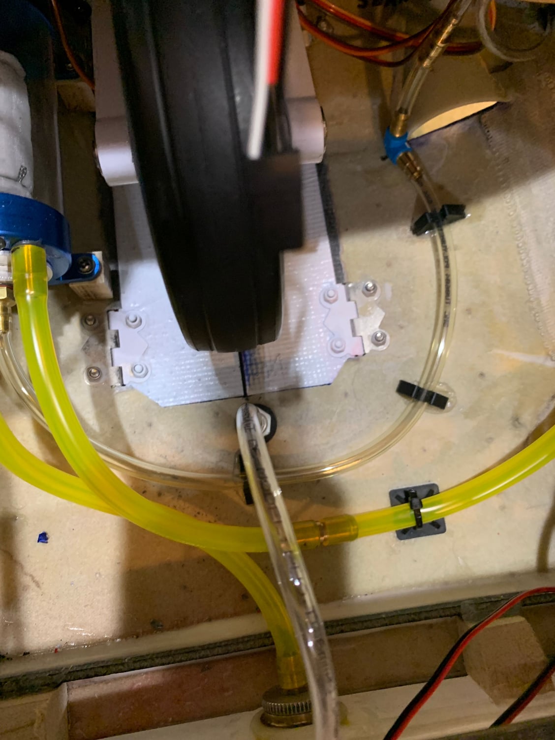
Clear vent tubing
Clear vent tubing