


Design KI1603 X-WRAE
 04-05-2020, 09:07 AM
#51

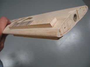
Used the planer to trim leading and trailing edges down and sanded flush to match ribs.
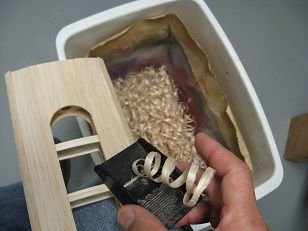
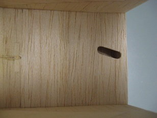
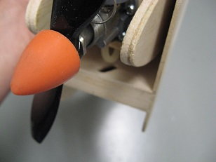
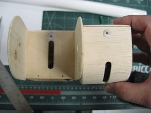
Backed up sandwiching root rib with #11 X-Acto blade while razor-sawing to create notch for control horns in all the flying surfaces. Placed horns and sanded root ribs flush with horns.
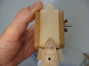
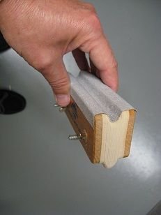
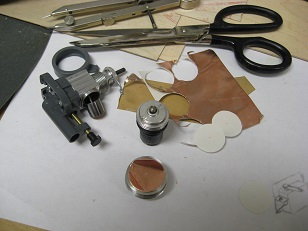
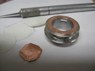
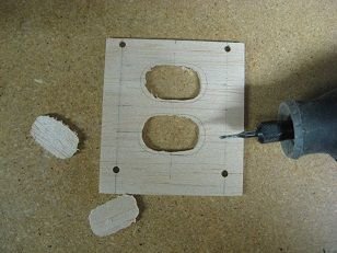
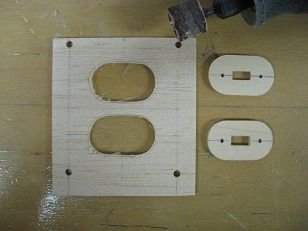
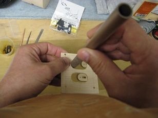
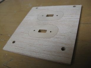
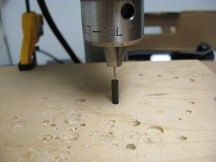
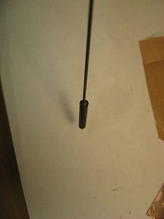
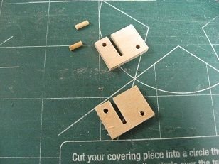
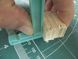
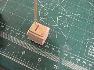
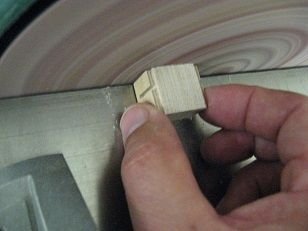
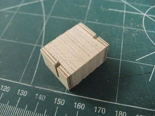
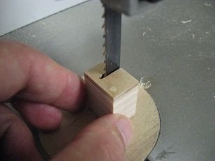
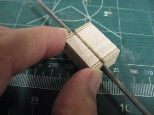
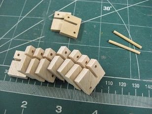
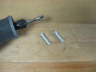
Drilled holes in a piece of scrap 1/4" lite ply - first with a brad-point followed with plain drill for blind nut - provided a flat to fill with 30 min epoxy, then blind nut inserted w/ 4-40 screw "handle". Cut all fabricated nut plates apart and trimmed down for turning in a drill press. These nut plates are to be bonded into the ends of all carbon tubes (wings and hinge knuckle) to accommodate a retention screw and washer. I'm turning them down in pairs with the drill press and Dremel - the cut-off wheel works better than the drum sander in this application - the nut is getting hot destroying the bond with the epoxy. There's always a better way to do something and I don't know it.


Backed up sandwiching root rib with #11 X-Acto blade while razor-sawing to create notch for control horns in all the flying surfaces. Placed horns and sanded root ribs flush with horns.
Drilled holes in a piece of scrap 1/4" lite ply - first with a brad-point followed with plain drill for blind nut - provided a flat to fill with 30 min epoxy, then blind nut inserted w/ 4-40 screw "handle". Cut all fabricated nut plates apart and trimmed down for turning in a drill press. These nut plates are to be bonded into the ends of all carbon tubes (wings and hinge knuckle) to accommodate a retention screw and washer. I'm turning them down in pairs with the drill press and Dremel - the cut-off wheel works better than the drum sander in this application - the nut is getting hot destroying the bond with the epoxy. There's always a better way to do something and I don't know it.

The following users liked this post:
mgnostic (04-06-2020)
04-17-2020, 04:43 PM
#52
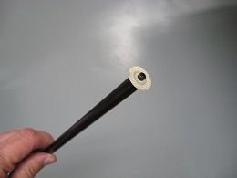
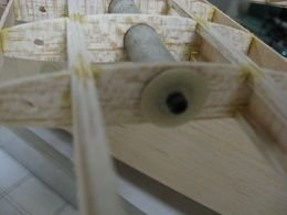
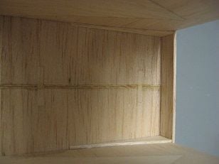
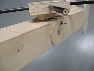
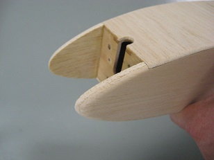
Managed to get enough (6) usable nut plates to populate the open ends of all the carbon tubes. Concern over similar mat'l friction and wear from vibration prompted fabricating 1/64" ply washers to fit between ends of 'glass sleeves and retention washers. These ply washers were glued to the ribs in the four panels to spread out the bearing surface some. Waxed the 'glass retention washers and 4-40 socket head screws and assembled to act as a depth stop when bonding them into the ends of the tubes. All the carbon tubes needed careful shortening to eliminate end play; a white ink pen found in Hobby Lobby came in real handy here. Using another tube of equal OD and a close fitting tube to fit the ID was of benefit to remove the hinge knuckle tube while maintaining alignment of all the spacer washers and fore/aft fuse sections. When satisfied with final lengths, the tubes were ready to be populated with the nut plates. A Permagrit sanding tool was employed - wrapped with tape to limit depth and sanded the areas inside the tubes to give them some 'tooth'. The tubes were cleaned out with acetone; Hysol was used to bond the nut plates in simply because it always seemed tough without ever becoming brittle. Excess glue was knocked off after cure; last pic shows retention bolt and washer holding wing panel with 'glass sleeve on the carbon spar tube.


The following users liked this post:
mgnostic (04-18-2020)
04-19-2020, 05:51 AM
#53
Ref: Fiberglass bearing tube length in each panel is ~ 4.015"; carbon tubes trimmed w/ repetitive fit chks to eliminate end play.
Using term spar tube interchangeably with pivot tube to denote carbon tubes for wing panels in previous post.
Little bit concerned over selection of 1/16" vs 1/32"...
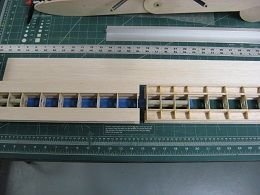
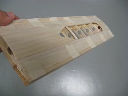
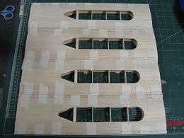
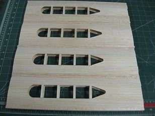
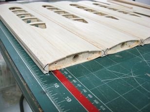
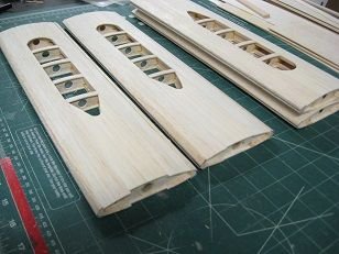
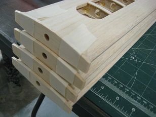
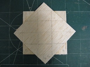
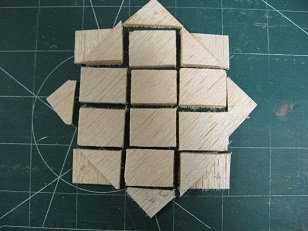
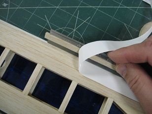
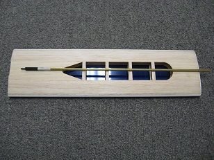
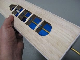
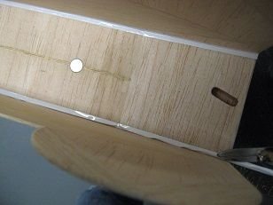
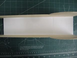
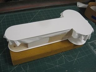
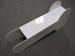
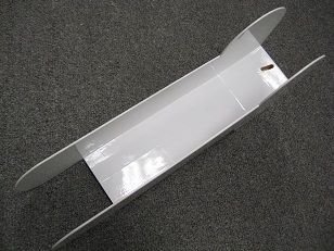
Since the major areas to get sheeting are right at 1" width (LE & TE), selected 4 sheets of 3" W 1/16" T sheeting to get enough material w/ excess to place 4 pcs on each panel - cutting right to size is risky. Cut 36" sht down to 30.5" L and cut width to 1.25" - cut in half for 15.25" lengths for some overhang on each panel (yielded 16 pcs). Placed sheet between T-pins to anchor on work surface and starting at the spar, applied white glue to this area only, placed panel against sheet using pins as guide to ensure alignment with spar - shimmed trailing side for first piece on each panel - started with bottoms. When dry, lifted sheeted wing assy from work surface, wet exposed surface with Windex, and even though considered against the law to use CA on balsa in certain parts of the Country, used thin variety to bond the remaining part of the sheeting to the ribs and sub LE/TE w/ capillary action. With all the bottom sheets attached, did same to top pcs - used more illegal, mid-grade CA w/ tip extension to apply glue to top of ribs - now I know why it would have been better to install the sheer webbing from the "backside" of the spars AFTER sheeting as would allow inspection and access to rib contact point w/ sheeting during closeout.
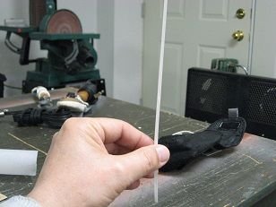
Last pic shows planing off excess sheeting; panels stiff in twisting now.


Using term spar tube interchangeably with pivot tube to denote carbon tubes for wing panels in previous post.
Little bit concerned over selection of 1/16" vs 1/32"...
Since the major areas to get sheeting are right at 1" width (LE & TE), selected 4 sheets of 3" W 1/16" T sheeting to get enough material w/ excess to place 4 pcs on each panel - cutting right to size is risky. Cut 36" sht down to 30.5" L and cut width to 1.25" - cut in half for 15.25" lengths for some overhang on each panel (yielded 16 pcs). Placed sheet between T-pins to anchor on work surface and starting at the spar, applied white glue to this area only, placed panel against sheet using pins as guide to ensure alignment with spar - shimmed trailing side for first piece on each panel - started with bottoms. When dry, lifted sheeted wing assy from work surface, wet exposed surface with Windex, and even though considered against the law to use CA on balsa in certain parts of the Country, used thin variety to bond the remaining part of the sheeting to the ribs and sub LE/TE w/ capillary action. With all the bottom sheets attached, did same to top pcs - used more illegal, mid-grade CA w/ tip extension to apply glue to top of ribs - now I know why it would have been better to install the sheer webbing from the "backside" of the spars AFTER sheeting as would allow inspection and access to rib contact point w/ sheeting during closeout.
Last pic shows planing off excess sheeting; panels stiff in twisting now.
05-23-2020, 10:22 AM
#54
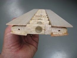
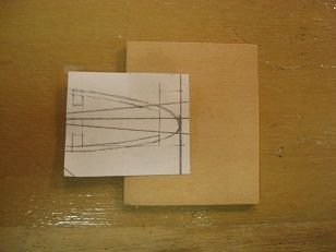
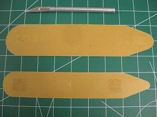
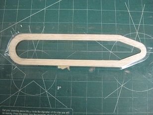
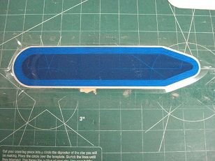
Traced center root and tip wing sheeting off drawing, cut templates from cardstock, and cut blanks to fit and glue between LE/TE sheeting. Used double-face tape to stack all blanks together and cut at same time creating identical copies (8 roots & 8 tips) Fit and glued first inboard 1/4" W cap strips to index location of root sheet pieces.


The following users liked this post:
mgnostic (05-24-2020)
06-17-2020, 04:36 PM
#55
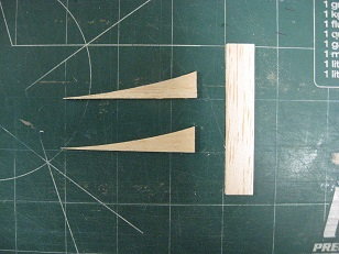
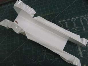
Leading edges comprised of 1/2" x 1/4" sticks from a Tower "Box-A-Sticks" that were super hard, dense balsa B-C grain. Cut long, glued on with white glue and taped to dry.
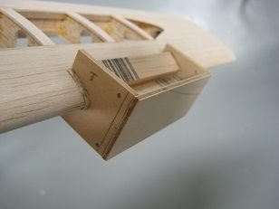
Marked the high point of the radius for LE and TE of each wing panel - justified slightly to the bottom of the airfoil. Shaped the leading/trailing edges with a sanding block by hand and was concerned with uniformity between surfaces -
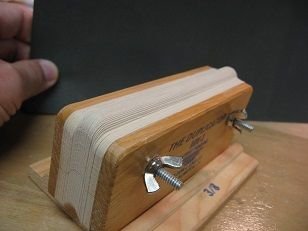
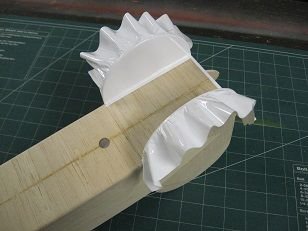
I possess a tool that is designed to shape LE's - but only on constant chord style wings as it wouldn't work on a tapered wing panel; it works like a contour gauge with a series of cards all sandwiched together with slotted holes to allow positioning for different radii. I tried it here but didn't like the results from lack of patience/experience using this tool and ended up fabricating a dedicated tool for the task.
Also added the rest of the 1/16" x 1/4" cap strips and the tip closeouts (1/8" balsa).
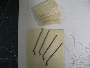
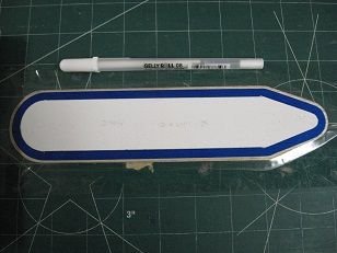
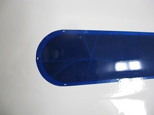
Depth stops double-stick taped to wing panel
Sandpaper applied to E. J. Lind Duplicator -
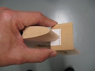
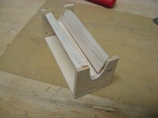
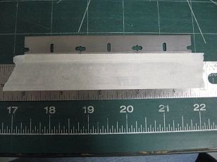
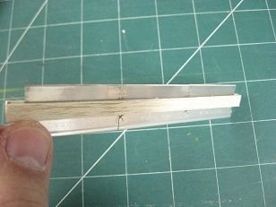
3" long dedicated sanding tool -
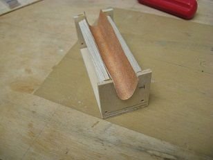
3M 77'd sandpaper in place on tool -
Marked the high point of the radius for LE and TE of each wing panel - justified slightly to the bottom of the airfoil. Shaped the leading/trailing edges with a sanding block by hand and was concerned with uniformity between surfaces -
I possess a tool that is designed to shape LE's - but only on constant chord style wings as it wouldn't work on a tapered wing panel; it works like a contour gauge with a series of cards all sandwiched together with slotted holes to allow positioning for different radii. I tried it here but didn't like the results from lack of patience/experience using this tool and ended up fabricating a dedicated tool for the task.
Also added the rest of the 1/16" x 1/4" cap strips and the tip closeouts (1/8" balsa).
Depth stops double-stick taped to wing panel
Sandpaper applied to E. J. Lind Duplicator -
3" long dedicated sanding tool -
3M 77'd sandpaper in place on tool -
The following users liked this post:
mgnostic (06-18-2020)
07-05-2020, 02:46 PM
#56
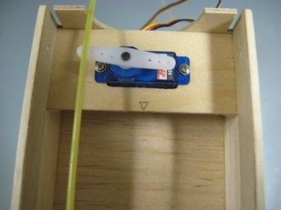
A 1/32" ply side mount for the throttle servo was abandoned in favor of a tray as the front fuse side separation points don't allow flat areas for bonding - fabricated from 1/16th ply with 1/8" lite-ply doublers for more screw bite - predicted nose-heaviness allows aft-most positioning of throttle servo -
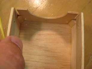
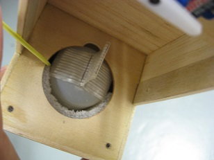
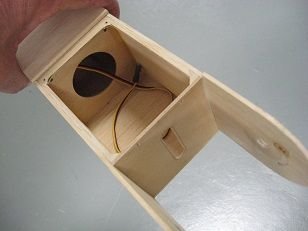
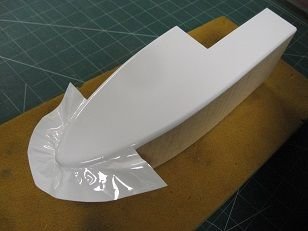
Located tank feed line hole in fuse bottom sheeting and vent hole in firewall; fabricated a custom foam cradle to position and immobilize tank; added a tape pull tab to facilitate tank removal - clearance for tank vent blister was added to top of hole on former, F-2 -
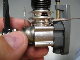
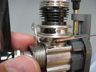
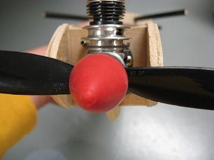
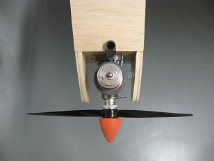
I've never used exhaust throttle on Cox engines before - installation presented numerous challenges to get it working satisfactorily - ended up using a braided cable (not pictured) with .047" Z-bent wire soldered to end attaching to throttle snap-ring.
Final coat of epoxy resin to tank compartment and sealed up fwd fuse with top sheeting, opened up hole for choke tube, and sanded excess sheeting flush -
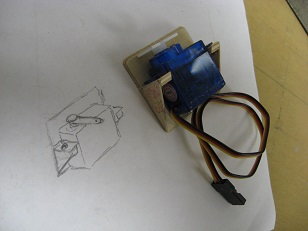
Unused servo mount -
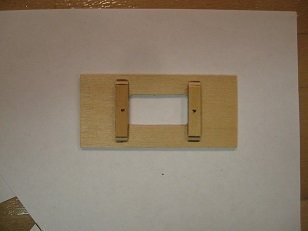
Substitute servo tray -
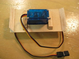
Throttle servo in mount with tri-stock gussets -
Intended throttle servo location at aft end of fwd fuse -

Fuel tank cradle fashioned from Ethafoam on bandsaw -
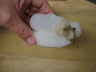
Tank in cradle -

Tank in position; note vent line poking through firewall -
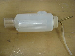
Fuel tank access pull-tab -
WOT?
Throttle cut? (I hope) -
Shimming the throttle sleeve to eliminate slop w/ 4 layers of copper tape -
X-Acto knife used to trim out center of shims -
Throttle linkage installation -
Front end before rounding off all corners -
Throttle servo tentative position -
Notch filed in former for tank blister clearance -
Located tank feed line hole in fuse bottom sheeting and vent hole in firewall; fabricated a custom foam cradle to position and immobilize tank; added a tape pull tab to facilitate tank removal - clearance for tank vent blister was added to top of hole on former, F-2 -
I've never used exhaust throttle on Cox engines before - installation presented numerous challenges to get it working satisfactorily - ended up using a braided cable (not pictured) with .047" Z-bent wire soldered to end attaching to throttle snap-ring.
Final coat of epoxy resin to tank compartment and sealed up fwd fuse with top sheeting, opened up hole for choke tube, and sanded excess sheeting flush -
Unused servo mount -
Substitute servo tray -
Throttle servo in mount with tri-stock gussets -
Intended throttle servo location at aft end of fwd fuse -
Fuel tank cradle fashioned from Ethafoam on bandsaw -
Tank in cradle -
Tank in position; note vent line poking through firewall -
Fuel tank access pull-tab -
WOT?
Throttle cut? (I hope) -
Shimming the throttle sleeve to eliminate slop w/ 4 layers of copper tape -
X-Acto knife used to trim out center of shims -
Throttle linkage installation -
Front end before rounding off all corners -
Throttle servo tentative position -
Notch filed in former for tank blister clearance -
The following users liked this post:
mgnostic (07-06-2020)
07-19-2020, 10:17 AM
#57
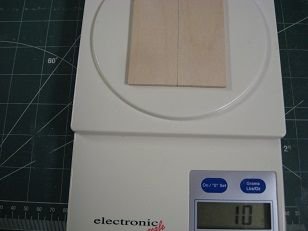
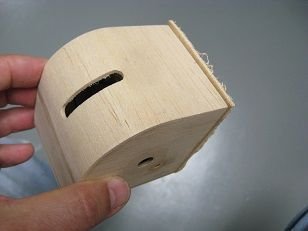
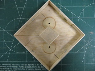
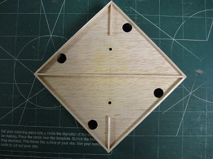
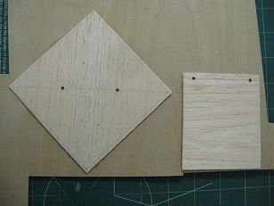
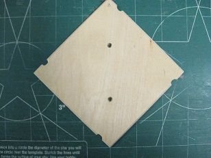
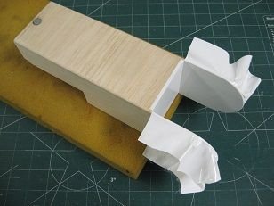
I wanted to mount the switch harness and charge port in the airplane. Fabrication of a hatch cover for the hinge knuckle interface would accommodate these two items - a simple lite-ply hatch was weighed against component parts (except glue) to make up an identical-sized hatch using balsa for a majority of it and I was happy to see that it could make a significant difference.
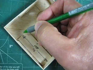
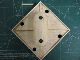
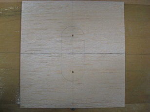
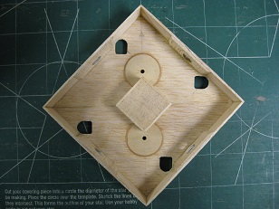
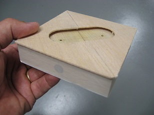
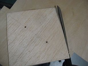
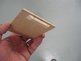
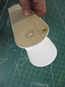
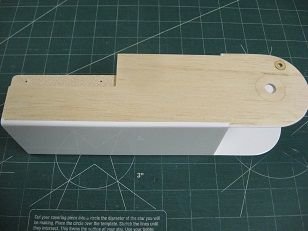
After installing hardpoints and drilling to accept sheet-metal fastening screws in the four corners of the hinge knuckle interface, the mostly balsa exterior for the hatch was dealt with - cut oversize, it fits up against the top lip of the wing pylon mounting plate. By installing the four screws, locating just one of the holes allows the part to be placed on the one screw and simply pressing the balsa hatch against the other three corner screws leaves an impression to locate the other holes exactly where they need to be. The holes are opened up with a Permagrit tool that is the same diameter as the hex head of the screw. The hatch is perimeter oversize at this point and will be sanded to size at completion.
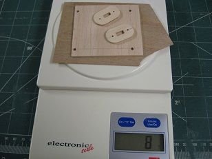
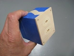
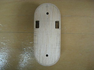
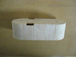
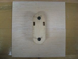
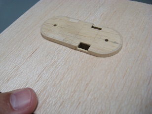
Localized hard-points for the switch mount and charge port mount were cut and shaped into two 1/8" lite-ply oval shape pieces. 3/32" balsa made up the majority with a 1/64" ply back/stiffener; the balsa cover was opened up to accept the two hardpoints as an inlay and the 1/64" ply back (also perimeter oversize) was bonded to the balsa facing with 30 minute epoxy applied to both mating surfaces and scraped off leaving minimal amount and weighted/clamped to set. The face of the hatch was sanded to get the ply inlays flush with the balsa exterior. After opening up the holes - now only large enough for the threaded body of the screw - and screwing the hatch cover to the knuckle interface, it is sanded to perimeter size to complete the part. My low budget scale only has resolution to 2 gram increments but the all-ply hatch shows approx 6 grams heavier than the built-up, "composite" hatch cover -
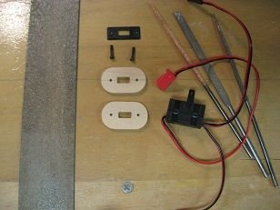
Fabrication of two 1/8" lite ply mounting plates -
1/8" lite play hatch cover for comparison -
Raw mat'ls to make up "composite" hatch cover -
Hatch screws installed in the hinge knuckle interface -
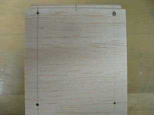
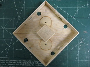
First of the four screw heads located in "oversize" 3/32" balsa sheeting -
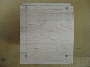
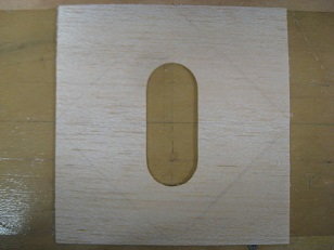
Remaining three screw holes opened up to fit screw heads -
Rough-outs for hard points w/ carbide burr -
Large drum sander came in handy here -
Final fits by hand -
Inlays installed and sanded -
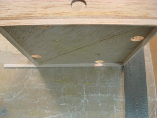
Laminated hatch installed on hinge knuckle interface -
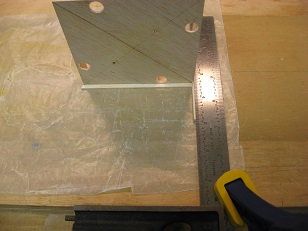
Tape barrier prep for sanding hatch cover perimeter -
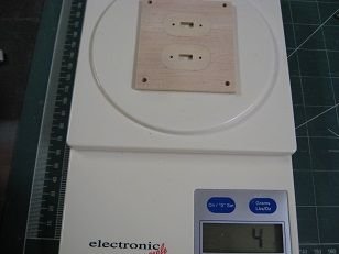
Final weight of built-up hatch cover -
After installing hardpoints and drilling to accept sheet-metal fastening screws in the four corners of the hinge knuckle interface, the mostly balsa exterior for the hatch was dealt with - cut oversize, it fits up against the top lip of the wing pylon mounting plate. By installing the four screws, locating just one of the holes allows the part to be placed on the one screw and simply pressing the balsa hatch against the other three corner screws leaves an impression to locate the other holes exactly where they need to be. The holes are opened up with a Permagrit tool that is the same diameter as the hex head of the screw. The hatch is perimeter oversize at this point and will be sanded to size at completion.
Localized hard-points for the switch mount and charge port mount were cut and shaped into two 1/8" lite-ply oval shape pieces. 3/32" balsa made up the majority with a 1/64" ply back/stiffener; the balsa cover was opened up to accept the two hardpoints as an inlay and the 1/64" ply back (also perimeter oversize) was bonded to the balsa facing with 30 minute epoxy applied to both mating surfaces and scraped off leaving minimal amount and weighted/clamped to set. The face of the hatch was sanded to get the ply inlays flush with the balsa exterior. After opening up the holes - now only large enough for the threaded body of the screw - and screwing the hatch cover to the knuckle interface, it is sanded to perimeter size to complete the part. My low budget scale only has resolution to 2 gram increments but the all-ply hatch shows approx 6 grams heavier than the built-up, "composite" hatch cover -
Fabrication of two 1/8" lite ply mounting plates -
1/8" lite play hatch cover for comparison -
Raw mat'ls to make up "composite" hatch cover -
Hatch screws installed in the hinge knuckle interface -
First of the four screw heads located in "oversize" 3/32" balsa sheeting -
Remaining three screw holes opened up to fit screw heads -
Rough-outs for hard points w/ carbide burr -
Large drum sander came in handy here -
Final fits by hand -
Inlays installed and sanded -
Laminated hatch installed on hinge knuckle interface -
Tape barrier prep for sanding hatch cover perimeter -
Final weight of built-up hatch cover -
The following users liked this post:
mgnostic (07-20-2020)
08-08-2020, 04:22 PM
#58
Haste makes waste - rushing the project resulted in overlooking an essential requirement and that is to get wiring from the flying/control surfaces in the control distribution center section to the receiver located in the fwd fuse section. Ended up locating holes in the floor of the center section and adding a subfloor as a pass through for wiring into the pylon and down into the hinge knuckle -
Locating the four pass-through holes in the floor of cntr section -
Four holes marked -
Holes tangent to walls of cntr section -
Adding 1/16" T subfloor walls -
Last piece -
Addition of subfloor support spacers -
Fitting pylon -
Pass-through for servo connectors and wiring in pylon -
Top holes allow for connector clearance on sides from subfloor -
Blank sheeting to fit hole for pylon on subfloor -
Lay out for hole -
Subfloor hole fit of pylon -
Slight oversize perimeter layout of subfloor from holed blank -
Revised holes for connector clearance -
Sub-floor installation on control distribution center section -
The following users liked this post:
mgnostic (08-09-2020)
08-16-2020, 03:37 PM
#59
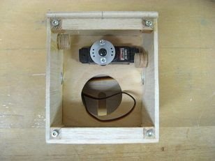
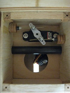
A .155" hole was drilled in drill block to hold release pins for master hinge knuckle while drilling. Pins were drilled out for .047" wire and checked for trueness then roughed-up wires bonded in with Hysol. Because the output wheel holes aligned with holes in the sides of the master hinge knuckle only in neutral position on servo, alignment at servo endpoints caused quite a bit of flexing and binding issues so another arm was substituted to split the difference between servo center and end points to "balance" linear action from the rotary output -
Chuck choked up on drill to reduce flexing -
Rotating wire to check for trueness of hole -
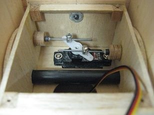
Output wheel replaced with twin output arm -
Chuck choked up on drill to reduce flexing -
Rotating wire to check for trueness of hole -
Output wheel replaced with twin output arm -
The following users liked this post:
mgnostic (08-17-2020)
09-19-2020, 09:04 AM
#60
Using the stiff music wire pull/push rods seen in above post, the action didn't work well with lots of binding issues trying to get rotary motion to translate into linear motion for the release mechanism. Conversation with an engineer and his suggestion to pull with something flexible like string or line resulted in my substitution to use braided cable; it now works very well and is still stiff enough over the short length to reset without fiddling.
Center points of the four flight control servos were set and the four arm, output horns were clocked until positions were identical for all four servos. Output horns were marked and modified to eliminate the three unused arms, then cleaned up.
Looks good but is wrong! Need mirror image -
Correct orientation and position of output horn -
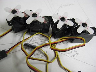
Four servo output horn arms indexed and marked for amputations -
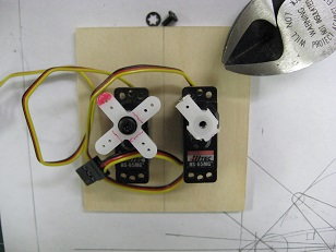
Trimming arms with dikes -
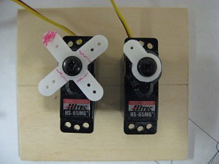
Arm sanded to clean up cuts -
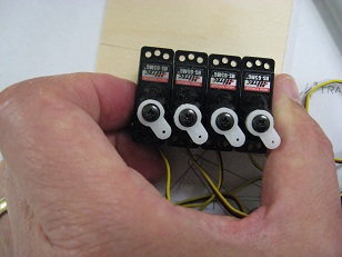
All four setup and ready for install -
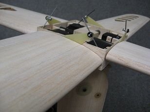
Servo floor spacers and Initial pushrod fabrication - pushrods will be captured so "Z" bends are unnecessary -
Mounting of the four distribution center section servos posed an obstacle in lightweight ideas and consultation advice resulted in a simple lightweight solution by lamination of triple-layer balsa plywood from which to cut slotted mounts that would capture the servo's mounting flanges between the floor and hatch.
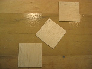
Three pieces of 1/16" balsa sheet oriented to create balsa ply -
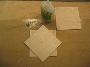
Laminating -
Balsa ply -
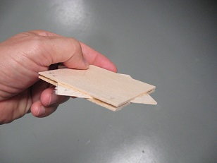
Layout of eight pieces needed for servo mounts -
Cuts for eight blanks -
Center points of the four flight control servos were set and the four arm, output horns were clocked until positions were identical for all four servos. Output horns were marked and modified to eliminate the three unused arms, then cleaned up.
Looks good but is wrong! Need mirror image -
Correct orientation and position of output horn -
Four servo output horn arms indexed and marked for amputations -
Trimming arms with dikes -
Arm sanded to clean up cuts -
All four setup and ready for install -
Servo floor spacers and Initial pushrod fabrication - pushrods will be captured so "Z" bends are unnecessary -
Mounting of the four distribution center section servos posed an obstacle in lightweight ideas and consultation advice resulted in a simple lightweight solution by lamination of triple-layer balsa plywood from which to cut slotted mounts that would capture the servo's mounting flanges between the floor and hatch.
Three pieces of 1/16" balsa sheet oriented to create balsa ply -
Laminating -
Balsa ply -
Layout of eight pieces needed for servo mounts -
Cuts for eight blanks -
Last edited by H5606; 09-19-2020 at 09:09 AM.
The following users liked this post:
mgnostic (09-20-2020)
09-21-2020, 04:44 PM
#61
Endplate patterns were fashioned from 1/8" ply pieces pinned together and a slot wide and deep enough to capture servo mounting tabs was cut and filed into them. The balsa blanks were sandwiched between them, drilled, pinned in like manner, with slot cut and filed to create duplicates.
1/8" ply endplate patterns - pinning holds all parts between patterns to create identical duplicates -
Ensuring parts are square before drilling to pin -
Balsa blanks sandwiched between endplates -
Balsa mounts sanded to size -
Perimeter sanded prior to slotting -
Bandsaw cuts slot -
Permagrit sanding tool finishes slot -
Pins and endplate patterns removed -
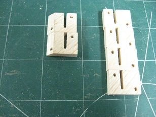
Ends are beveled on four to clear connector holes in center section floor -
1/8" ply endplate patterns - pinning holds all parts between patterns to create identical duplicates -
Ensuring parts are square before drilling to pin -
Balsa blanks sandwiched between endplates -
Balsa mounts sanded to size -
Perimeter sanded prior to slotting -
Bandsaw cuts slot -
Permagrit sanding tool finishes slot -
Pins and endplate patterns removed -
Ends are beveled on four to clear connector holes in center section floor -
The following users liked this post:
mgnostic (09-23-2020)
09-22-2020, 04:40 PM
#62
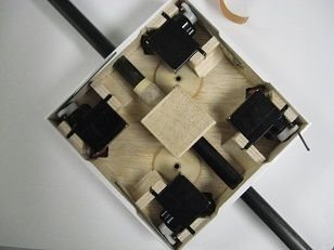
The servos were used to locate the 3/16" ply balsa mounts - four bonded to the walls of the distribution center section and four to the floor. 1/8" balsa spacers set the height of the servos from the floor of the center section.
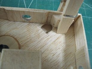
3/16" balsa ply servo mount clamped to center section wall -
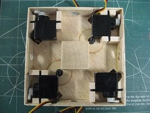
Some allowance and fitting to clear floor retention doublers of two of the mounts -

Triangle stock added to corners of inside servo mounts -
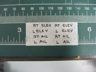
ID labels for servo leads at receiver -
3/16" balsa ply servo mount clamped to center section wall -
Some allowance and fitting to clear floor retention doublers of two of the mounts -
Triangle stock added to corners of inside servo mounts -
ID labels for servo leads at receiver -
The following users liked this post:
mgnostic (09-23-2020)
11-02-2020, 05:47 PM
#63
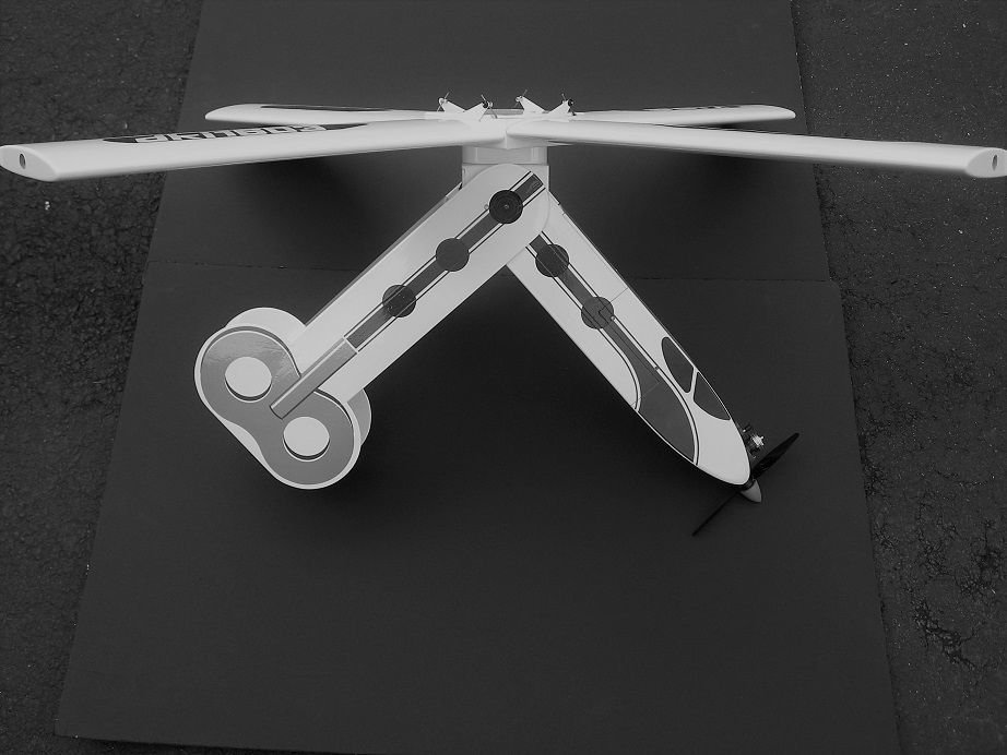
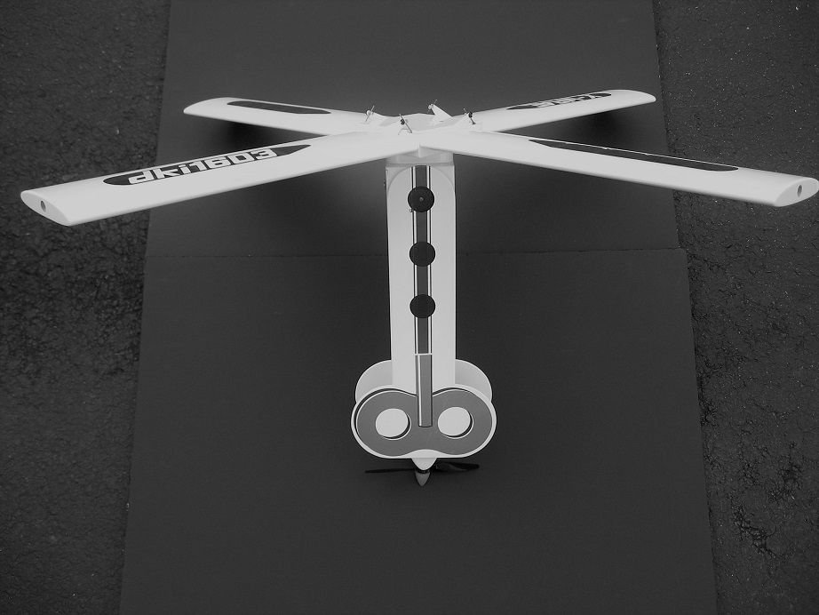
A program request for the desired mix and conditions was placed in the radio forum and thanks to Andy Kunz, a Spektrum development engineer that answers lots of questions, he set me up with a program file. After loading it into the transmitter, I'm able to operate in both modes: forward flight and autorotation after folding. For conventional flight, the forward two flying surfaces operate in like direction to control roll and the aft two flying surfaces operate in opposition to control pitch. After conversion and folding, the throttle stick is able to move the surfaces in a collective manner like a helicopter swashplate during autos.
Fabrication of a couple more hatches - one for receiver access and the other to close out the flight control center section - using balsa and 1/64" ply laminates.

Roll right, pitch up commanded -

Roll right, pitch up response (red arrow shows direction of fwd flight)
Showing collective deflections for all surfaces after commanding folding sequence; note rotation should be counterclockwise -
Turned down some 4-40 aluminum hex standoffs on the drill press for center section hatch retention -
Hatch fabrication - balsa/ply laminates
1/64" ply cuts well with scissors -
Receiver hatch retention means -
Receiver bay in fwd fuse section -
All hatches fit and sanded to size -
Fabrication of a couple more hatches - one for receiver access and the other to close out the flight control center section - using balsa and 1/64" ply laminates.
Roll right, pitch up commanded -
Roll right, pitch up response (red arrow shows direction of fwd flight)
Showing collective deflections for all surfaces after commanding folding sequence; note rotation should be counterclockwise -
Turned down some 4-40 aluminum hex standoffs on the drill press for center section hatch retention -
Hatch fabrication - balsa/ply laminates
1/64" ply cuts well with scissors -
Receiver hatch retention means -
Receiver bay in fwd fuse section -
All hatches fit and sanded to size -
Last edited by H5606; 11-02-2020 at 05:57 PM.
The following users liked this post:
mgnostic (11-03-2020)
11-03-2020, 07:15 AM
#64

Looking good!
11-03-2020, 09:24 AM
#65
Thanks!
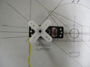
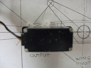
Amongst other concerns in this unchartered territory (for me), a new one cropped up recently while talking with an engineer - that being the full flying surfaces pivoting at the 1/2 chord and the resultant load on the servos...
Granted it would be a compromise in the autorotation mode but if they pivoted at the 1/4 chord, I'd have had the benefit of self-fairing due to relative wind. The way I have it now (pivoting at mid-chord) I'm thinking of it being sorta' like trying to carry a 4 x 8 sheet of plywood on your head against a 30 knot head wind.
I was trying to come up with a fix - either aerodynamic or mechanical (like a return spring) but weight, complexity, and laziness all come in to play here... so my plan to forge ahead even if it becomes a pitiful failure.
11-03-2020, 09:36 AM
#66
I would think scale factor would really come into play here. You are using relatively lightweight parts and flying at a relatively low airspeed. Things that would be a huge issue at twice the size are more manageable with a half-a aircraft. A full on digital servo might work if the HS-85s aren't enough.
01-03-2021, 09:13 AM
#67
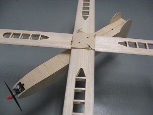
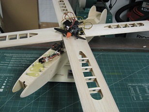
Calling the airframe complete sans covering -
The center section cover/hatch was not remaining flat with the original, ply/balsa sandwich, so another 1/64" skin was added above the balsa with major grain now running chordwise to stiffen the whole thing up.
The small box closeout or ramp mentioned back in post #47 was added to the ascend of the tail section and hole added to accommodate the fuel line with fuse in folded position. Triangle stock in the corners could have done the same job here...
All airframe components were sanded with edges and corners rounded.
One picture shows various hardware items that go into the airframe including horns, spacers, washers, screws, a receiver, battery, switch harness, engine, fuel tank, magnets, throttle and release servos, extensions, and spar carry-through.
Weight of the airplane at 21.5 ounces prior to covering.
Ply/balsa/ply center section hatch and notches to clear pushrods -
1/16" balsa ramp tail closeout component parts -
Installation -
1/16" sheeting and hole for fuel line -
Approaching nested position of fuel line -
Sanding...
Blending...
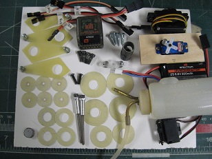
Internal components and missing here are the four flight control servos and ten hatch/assembly screws -
Piling everything on the scale -
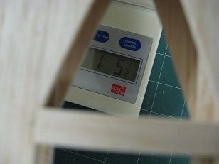
Weight of airplane prior to covering -
The center section cover/hatch was not remaining flat with the original, ply/balsa sandwich, so another 1/64" skin was added above the balsa with major grain now running chordwise to stiffen the whole thing up.
The small box closeout or ramp mentioned back in post #47 was added to the ascend of the tail section and hole added to accommodate the fuel line with fuse in folded position. Triangle stock in the corners could have done the same job here...
All airframe components were sanded with edges and corners rounded.
One picture shows various hardware items that go into the airframe including horns, spacers, washers, screws, a receiver, battery, switch harness, engine, fuel tank, magnets, throttle and release servos, extensions, and spar carry-through.
Weight of the airplane at 21.5 ounces prior to covering.
Ply/balsa/ply center section hatch and notches to clear pushrods -
1/16" balsa ramp tail closeout component parts -
Installation -
1/16" sheeting and hole for fuel line -
Approaching nested position of fuel line -
Sanding...
Blending...
Internal components and missing here are the four flight control servos and ten hatch/assembly screws -
Piling everything on the scale -
Weight of airplane prior to covering -
The following users liked this post:
mgnostic (01-04-2021)
02-28-2021, 03:04 PM
#68
Opening up the end-grain block supporting the carbon spar tubes at the intersection for the two that butt up against the single continuous length tube while maintaining alignment done by wrapping sand paper around tube - within the bounds of the center section.
Concern over orientation of hinge knuckle and wing panels after folding sequence prompted addition of magnets to this area.
Washers for the individual wing panels are held in place with short lengths of 1/16" square balsa and a long Allen hex-tool was fashioned to facilitate installation.
All small parts like hatches, the hinge knuckle, pylon, and center section housing were covered and holes opened up with a soldering iron. The spar tubes were Hysol'd in along with the short carry-through tube for the abutting tubes.
I wanted to be able to see the end of the spar tube during install or removal of the wing panels, so incorporated transparent covering in open structure areas. Made appropriate templates from G-10 to allow for 1/4" overlapping seams using opaque/transparent combo.
Tried something new here - ganged three single-edged razors together to make a longer cutting tool to trim Monokote with - it allows you to pull against a longer blade length before reposition for the next length of cut during the trimming process for excess Monokote. In order to get the single-edged blade ends to mate up against each other, some flush filing of the crimped-on handle is required.
Opening up one hole for spar carry-through reinforcing tube with sand paper wrap -
Add'l magnets added to ensure upright orientation of hinge knuckle to nose after folding sequence -
G-10 cutting templates - top for transparent panel; bottom for opaque window cutout -
Balsa covering stooge covered with packaging tape to make composite Monokote panels -
Transparent panel ironed down -
White pen used to place index marks for overlay panel centering -
Opaque panel ironed onto transparent window prior to removal from stooge -
Ganging three single-edged blades together to make a longer trimming tool -
Balsa strips and double-faced tape used to hold alignment of blades -
Trimming Monokote using this tool down against the covered part and pulling the excess against blade to shear -
Custom tool used to install/remove wing panels -
Tool access to spar tubes -
Last edited by H5606; 03-01-2021 at 04:34 AM. Reason: spelling/clarifications
The following users liked this post:
mgnostic (03-01-2021)
03-27-2021, 10:47 AM
#69
Continued covering process - aft fuselage - covered inside corners first, interior flats, then exterior, and top last.
1/4" strip of Monokote folded in half lengthwise creates an anchor to fit into corners for attaching large pieces of covering -
Covering interior corners using trim/seal tool -
Interior top -
Interior sides covered and heat-stretched around edges before trimming off excess -
Exterior corners and top sides of vertical fins done same way -
Exterior side Monokoted with support from nested forward fuselage to heat stretch perimeter edges prior to trimming excess -
Covered aft fuse section -
Interior of same -
Fwd fuse, aft fuse, and X-wing sections -
Same technique repeated on fwd fuse -
Following trimming and sealing edges -
Bottom covering edge trimmed with 3/32" balsa spacer, faced single-edge razor blade for a displaced cut, overlap allowance -
Last edited by H5606; 03-27-2021 at 02:58 PM. Reason: clarity
04-25-2021, 01:33 PM
#70
Finished base covering process with nose and looked at trim scheme -
Heat stretching covering at fwd nose section -
Fwd nose section trimmed before covering top -
Trim planning layouts -
Template pattern layout -
Basic trim applications -
Heat stretching covering at fwd nose section -
Fwd nose section trimmed before covering top -
Trim planning layouts -
Template pattern layout -
Basic trim applications -
Last edited by H5606; 04-25-2021 at 01:49 PM. Reason: Additions to captions
04-26-2021, 02:40 PM
#71
The airplane all-up weight after covering is 24.85 oz. -
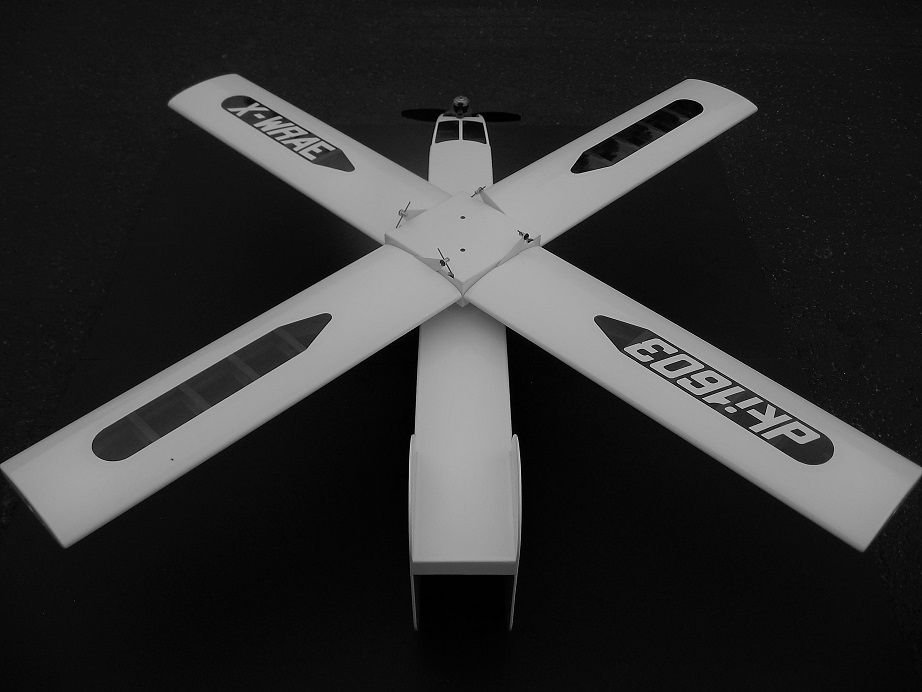
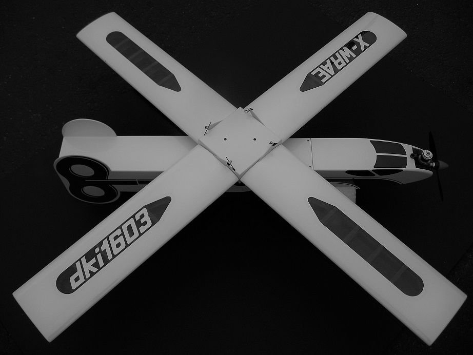
Each wing panel is 15" span with a 4" chord and the center section measures 4" square, so calling wing area 250 square inches - divided by 144 to get square feet -
24.85 oz. divided by 1.7361 square ft. = calculated wing loading of 14.31 oz. per sq. ft.
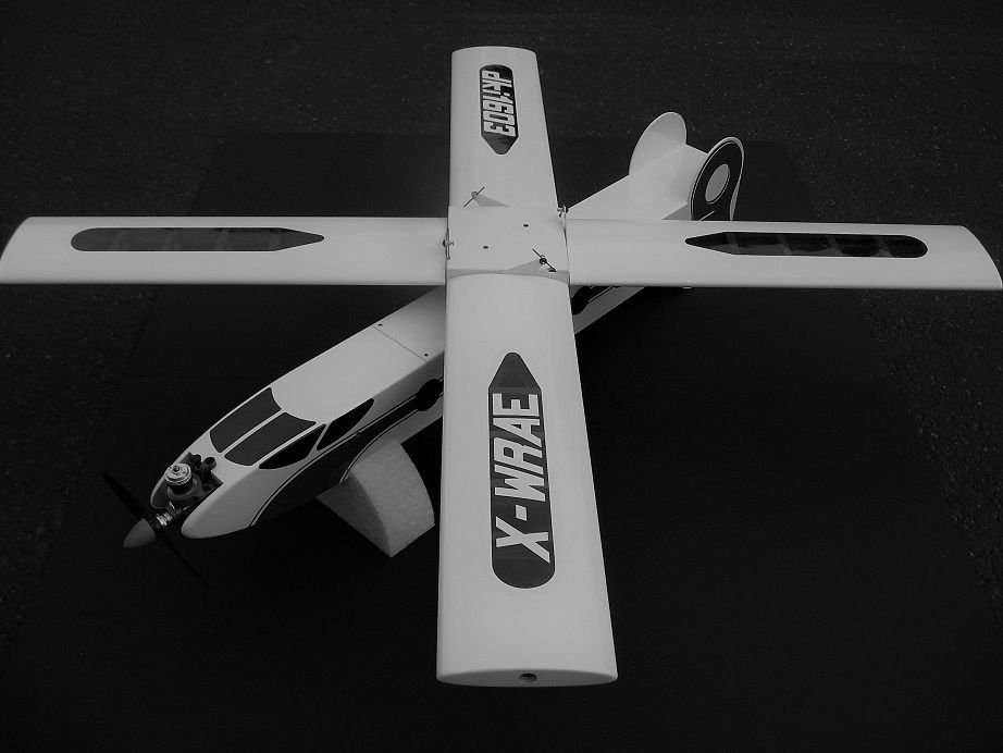
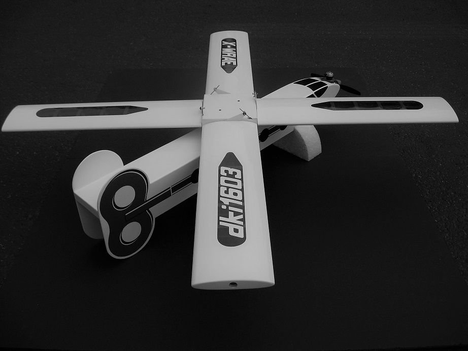
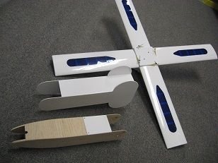
Forward flight mode -
Halfway through conversion -
Failsafe descent or destruct mode -
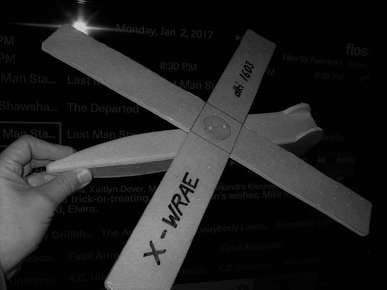
First prototype chuck glider from fan-fold-foam -
Each wing panel is 15" span with a 4" chord and the center section measures 4" square, so calling wing area 250 square inches - divided by 144 to get square feet -
24.85 oz. divided by 1.7361 square ft. = calculated wing loading of 14.31 oz. per sq. ft.
Forward flight mode -
Halfway through conversion -
Failsafe descent or destruct mode -
First prototype chuck glider from fan-fold-foam -
The following users liked this post:
mgnostic (04-27-2021)
04-27-2021, 07:42 AM
#72
it ended up as quite an attractive little airplane. Hope to hear of a maiden flight soon.

 05-09-2021, 01:30 PM
#74
Can't access my original YT account and opened a new one to demonstrate planned control functions and get vid uploads sorted out.
The 'X' measures 27" tip-to-tip square and called that dimension the MAC. Balance point computation: 10.5" back from 27" = 38.8% of MAC
I don't think there's enough negative deflection angle to promote optimal autorotation speed yet -
The 'X' measures 27" tip-to-tip square and called that dimension the MAC. Balance point computation: 10.5" back from 27" = 38.8% of MAC
I don't think there's enough negative deflection angle to promote optimal autorotation speed yet -
Last edited by H5606; 05-09-2021 at 01:47 PM. Reason: added thoughts
The following users liked this post:
mgnostic (05-10-2021)
06-17-2021, 06:11 PM
#75
Bluff:
-The airplane flew-
- A conversion for auto recovery was not attempted-
Details, notes, observations:
Flight lasted about 2 minutes 20 seconds. Amazing how time seems to slow down when the concentration and stress levels are high. Using a 900 MAh LiFe flight pack battery; engine is a Surestart with piston socket reset, crankcase backplate contact area lapped, high compression head w/ two shims, 6X3 Cox Nylon, and 25% Cox fuel. Removed throttle sleeve, linkage, throttle servo, rubber prop spinner, and ditched a 2"X3" .015" G-10, chin plate taped to the fwd belly prior to first flight to try to alleviate landing rash. Aforementioned items were removed to eliminate nose weight. The airplane flew with a high deck angle, wouldn't climb, and was extremely difficult to turn left.
Last edited by H5606; 06-18-2021 at 02:41 PM. Reason: Add'l info
The following users liked this post:
mgnostic (06-18-2021)