


Ziroli 92" p-47 build thread
 11-12-2014, 10:27 AM
#1

General info:
I used these plans to build the 110" P-47 and thought I'd build the 'regular' size version for smaller fields.
First, I want to assemble my Ziroli B-25 and then I'll start on this project.
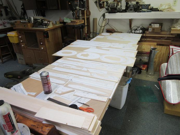
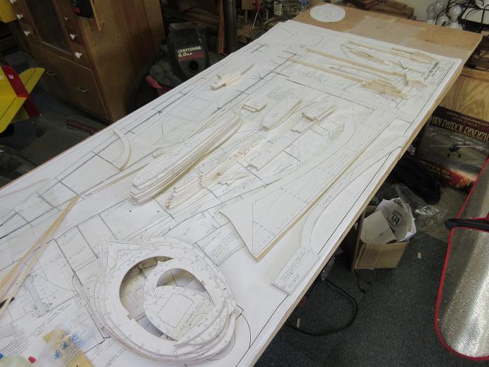
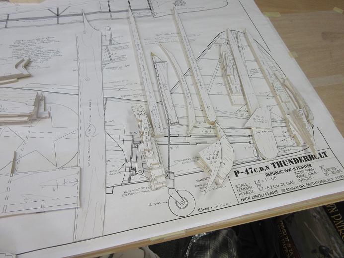
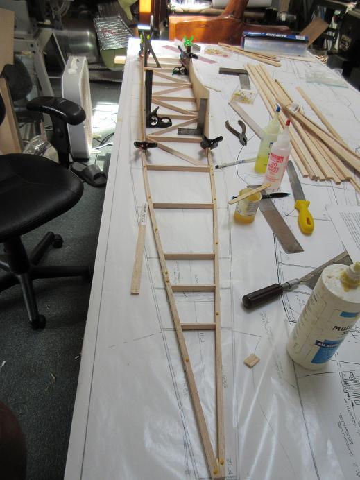
While setting up the work table for the winter, I thought I'd lay out the plans for the P-47 before covering them with blankets so I can then work on the B-25.
The wing plans were cut out and taped to the build table. The fuse plans were laid on another table.
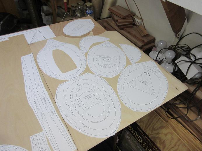
I'll be cutting all the parts so those templates were cut from the plans.
When I bought the plans, I also purchased the cowl and canopy.
Since I had a previous Z P-47, I've also got the gear.
A new DA-85 will be on the business end.
It will be a razor back with the usual functioning canopy and cowl flaps along with full gear doors.
As with the larger P-47, this one will also be done with aluminum tape.

 06-20-2015, 03:45 PM
#3
FCS,
Never have too many P-47's.
=============
Cutting the wood:
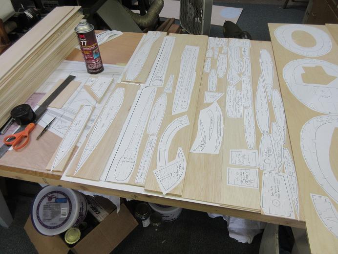
Used 3M spray adhesive on one surface to secure all paper cutouts to ply and balsa.
Lite ply formers (behind cockpit, except for tail gear former using aircraft ply):
Aircraft ply for inner ribs, wing saddles and front formers and a few other parts. Two sheets of aircraft ply glue sprayed together for those parts requiring two.

Balsa parts: from 2 to 4 sheets thick for some parts.
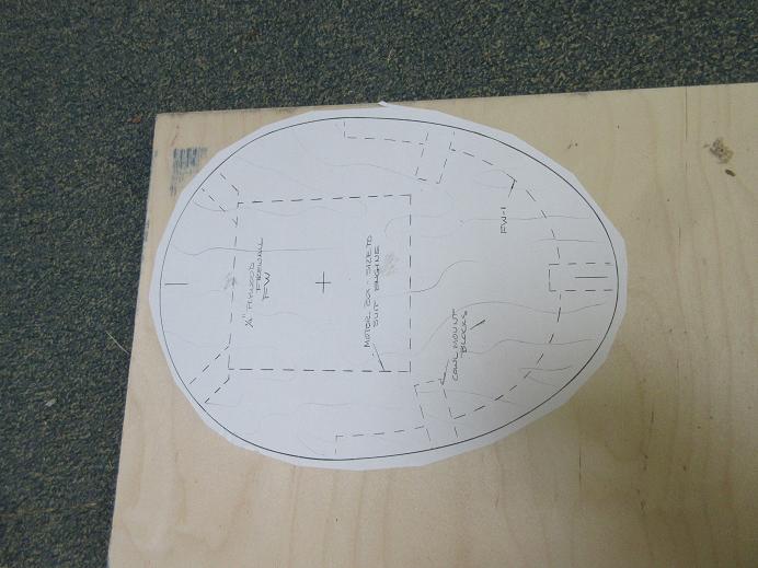
The fire wall will be removable and is on 1/2" thick aircraft ply.
3M spray:
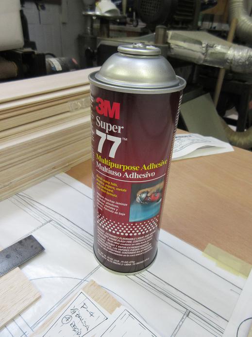
Next: start cutting and sanding all that wood.
Never have too many P-47's.
=============
Cutting the wood:
Used 3M spray adhesive on one surface to secure all paper cutouts to ply and balsa.
Lite ply formers (behind cockpit, except for tail gear former using aircraft ply):
Aircraft ply for inner ribs, wing saddles and front formers and a few other parts. Two sheets of aircraft ply glue sprayed together for those parts requiring two.
Balsa parts: from 2 to 4 sheets thick for some parts.
The fire wall will be removable and is on 1/2" thick aircraft ply.
3M spray:
Next: start cutting and sanding all that wood.
Last edited by samparfitt; 06-20-2015 at 03:51 PM.
06-23-2015, 01:42 PM
#5
Cutting parts (cont)
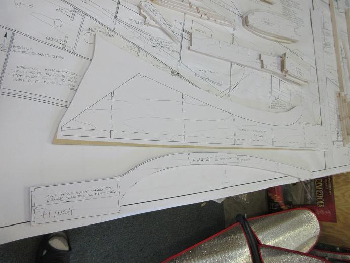
All the templates were cut with at least a 1/4" around the perimeter: Makes it easy to cut and sand to the line.
When cutting, I left a good 1/16' around all parts and then sand down to the line. Seems like when I cut on the line, I invariably go past the line, plus I can get a smoother surface by sanding.
Formers cut save FW (1/2" thick) and F-8 (ran out of 3 ply).
Still need to mark and cut for the stringers. Will mark for 1/4" square stringers versus 1/8"X1/4" as I like the larger surface area for gluing the sheeting.
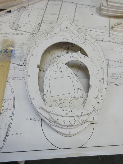
Ribs all cut: Everything to the R-7 are aircraft ply to support the gear. I've never had a gear go through the top of the wings, yet, and I've done some bad landings over the years! When I buy a kit, I have to re-cut a lot of formers and ribs as the plans call for aircraft ply on certain parts and the kit cutters don't use it, so it is usually easier just to cut my own parts. I cut inside the lines for stringers, spars, etc on the formers and ribs as the slots always seem to be a little too large: as Roy Underwood always says, it's easier to remove wood versus adding it!
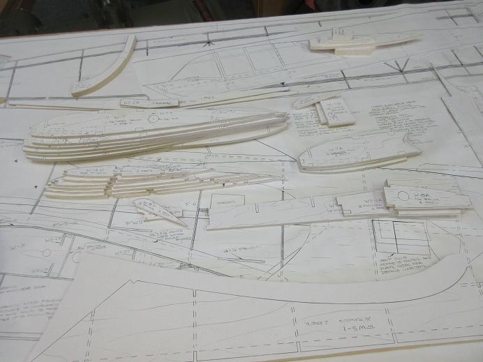
Horizontal stab, elevator, vertical fin and rudder:
Had to zerox the stab saddle from the fuse plans as I think that template is missing.
Pylon parts:
Wing saddles:
I screwed up cutting these. I make the nose an extra inch longer for weight savings and forgot to add it. Have to see if I can sister the extra inch to the saddles.
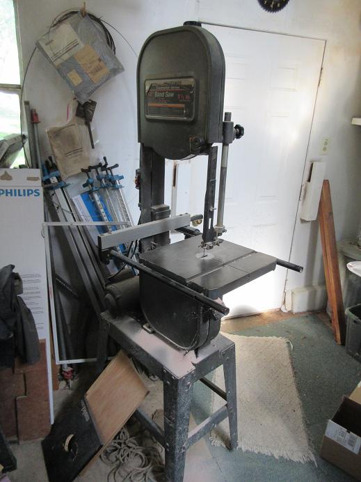
Tools of the trade:
The scroll saw and oscillating sander (one that a belt can be added to) are the main tools for cutting and sanding the parts.
Initially, I was going to use the floor model band saw but the throat is small so cross cutting is difficult. A dust mask and ear muffs as I'm not as tough as I used to be! (I remember when I was a kid, safety was for wimps!).
There's really not that many parts, the bulk of the wood will be the sheeting.
Even with a shop vac attached, it makes a mess. Being in the detached shop, it's easy to blow the mess out the garage door. If it's a warm day, I suggest taking the belt sander outside and saving from making a mess in the basement or worse (a spare room).

All the templates were cut with at least a 1/4" around the perimeter: Makes it easy to cut and sand to the line.
When cutting, I left a good 1/16' around all parts and then sand down to the line. Seems like when I cut on the line, I invariably go past the line, plus I can get a smoother surface by sanding.
Formers cut save FW (1/2" thick) and F-8 (ran out of 3 ply).
Still need to mark and cut for the stringers. Will mark for 1/4" square stringers versus 1/8"X1/4" as I like the larger surface area for gluing the sheeting.
Ribs all cut: Everything to the R-7 are aircraft ply to support the gear. I've never had a gear go through the top of the wings, yet, and I've done some bad landings over the years! When I buy a kit, I have to re-cut a lot of formers and ribs as the plans call for aircraft ply on certain parts and the kit cutters don't use it, so it is usually easier just to cut my own parts. I cut inside the lines for stringers, spars, etc on the formers and ribs as the slots always seem to be a little too large: as Roy Underwood always says, it's easier to remove wood versus adding it!
Horizontal stab, elevator, vertical fin and rudder:
Had to zerox the stab saddle from the fuse plans as I think that template is missing.
Pylon parts:
Wing saddles:
I screwed up cutting these. I make the nose an extra inch longer for weight savings and forgot to add it. Have to see if I can sister the extra inch to the saddles.
Tools of the trade:
The scroll saw and oscillating sander (one that a belt can be added to) are the main tools for cutting and sanding the parts.
Initially, I was going to use the floor model band saw but the throat is small so cross cutting is difficult. A dust mask and ear muffs as I'm not as tough as I used to be! (I remember when I was a kid, safety was for wimps!).
There's really not that many parts, the bulk of the wood will be the sheeting.
Even with a shop vac attached, it makes a mess. Being in the detached shop, it's easy to blow the mess out the garage door. If it's a warm day, I suggest taking the belt sander outside and saving from making a mess in the basement or worse (a spare room).
Last edited by samparfitt; 06-23-2015 at 02:13 PM.
06-24-2015, 11:16 AM
#6
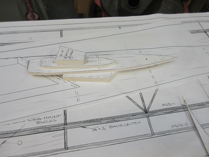
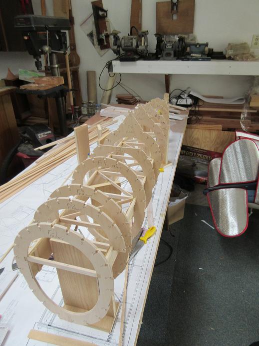
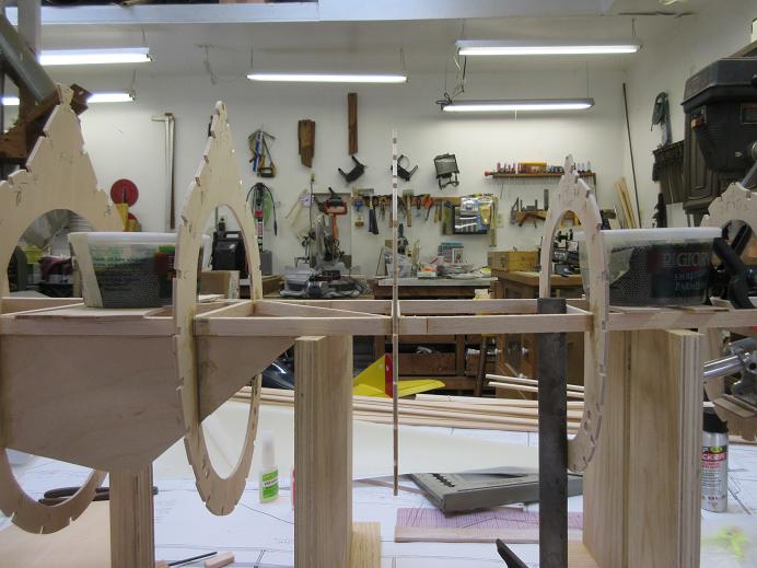
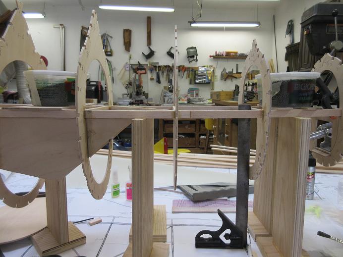
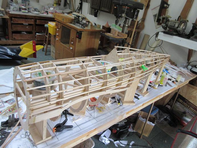
Fuse crutch.
The crutch keeps all formers aligned with each other.
Some wax paper over the plans before building the crutch.
For the most part I use polyvinyl acetate (PVA, elmer's wood glue) glue for the bulk of my building. If blobs aren't present, it dries fairly quickly, is cheap at about 15 bucks a gallon and very strong (good enough for furniture). Safe to move set up time of about 20 minutes: I usually have other parts to work on while it dries and good when set up time is needed for large parts.
The crutch nose was made 1 inch longer.
A heat gun is needed to easily remove the paper templates from the wood and separate multiple wood layers.
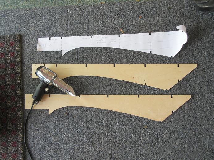
Seems like the notches in the wing saddle never align perfectly, so they are marked before cutting.
Wing saddles epoxied to the crutch. Sistered in a 1 inch extension on the front of the wing saddle to match the crutch length.

The crutch keeps all formers aligned with each other.
Some wax paper over the plans before building the crutch.
For the most part I use polyvinyl acetate (PVA, elmer's wood glue) glue for the bulk of my building. If blobs aren't present, it dries fairly quickly, is cheap at about 15 bucks a gallon and very strong (good enough for furniture). Safe to move set up time of about 20 minutes: I usually have other parts to work on while it dries and good when set up time is needed for large parts.
The crutch nose was made 1 inch longer.
A heat gun is needed to easily remove the paper templates from the wood and separate multiple wood layers.
Seems like the notches in the wing saddle never align perfectly, so they are marked before cutting.
Wing saddles epoxied to the crutch. Sistered in a 1 inch extension on the front of the wing saddle to match the crutch length.
Last edited by samparfitt; 06-24-2015 at 11:21 AM.
06-25-2015, 01:19 PM
#11
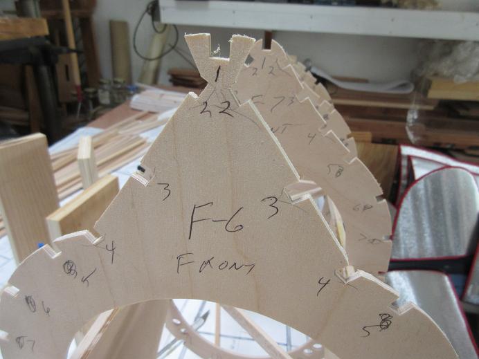
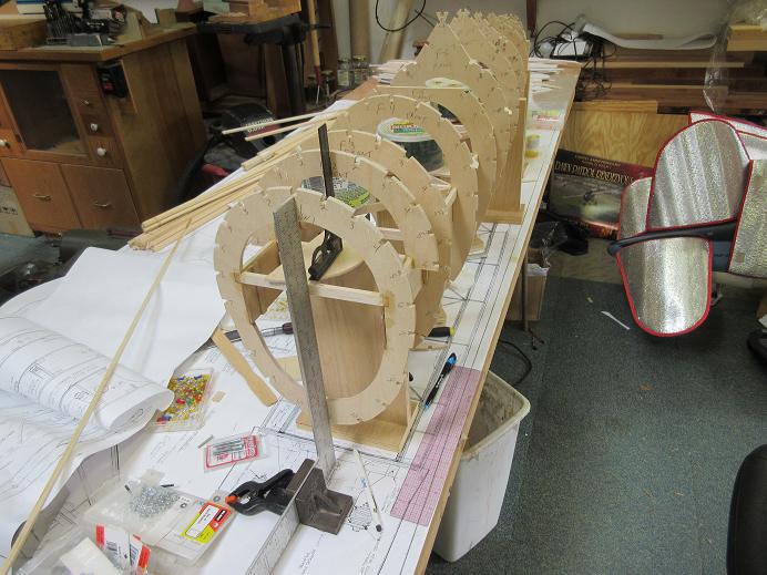
Formers (cont)
Got all the formers cut and dry fitted.
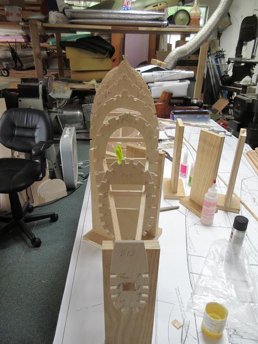
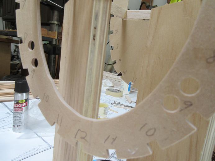
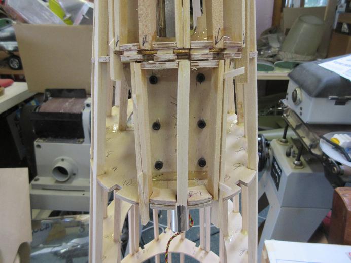
Cut extra notches (were none) in the formers to support the razor back.
Drilled 3/8" holes in the back formers to route wires and air lines.
Need to make mods to the formers for Darrell's tail gear.
Got all the formers cut and dry fitted.
Cut extra notches (were none) in the formers to support the razor back.
Drilled 3/8" holes in the back formers to route wires and air lines.
Need to make mods to the formers for Darrell's tail gear.
06-25-2015, 04:38 PM
#12
Formers (cont)
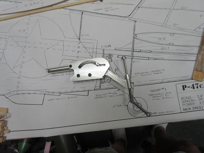
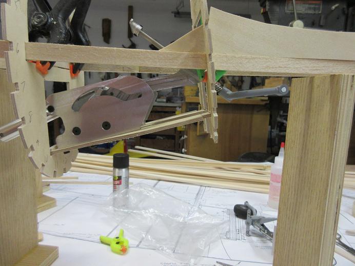
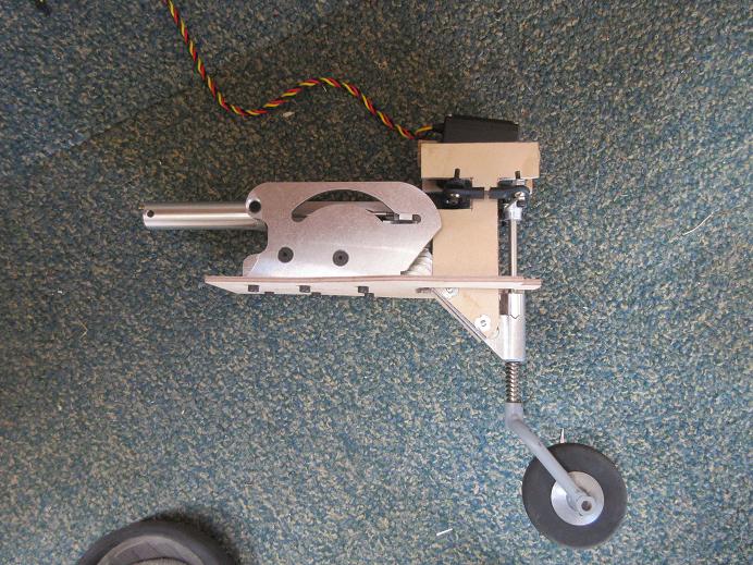
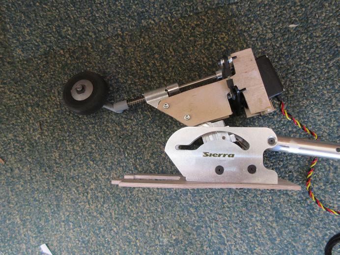
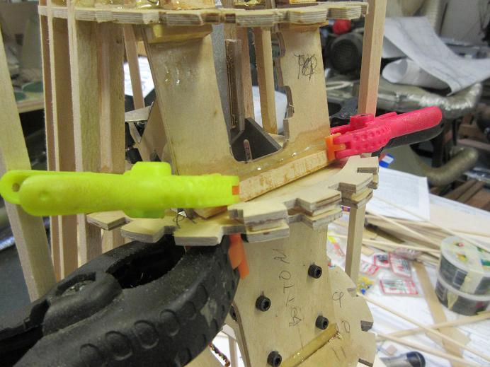
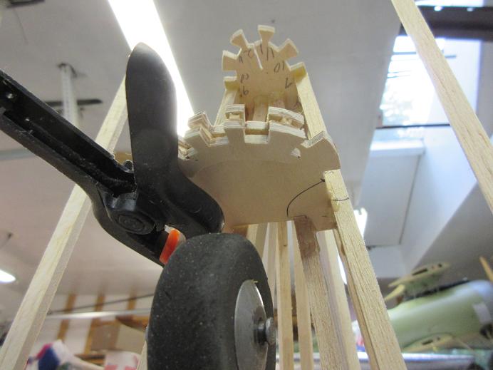
Tail gear.
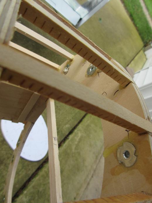
Darrell's tail gear is mounted horizontally, versus robart's vertically mounted. A ply plate was made to span F-10 to F-11. The F-10A former is for mounting robarts so that will be eliminated. All 1/8" thick aircraft ply. Slots cut into the two formers so the ply gear mount slides into each former by a 1/4", insuring no breaking due to glue failure.
There are six #6 screws holding the gear to the ply plate. An access hatch will be made on the bottom of the fuse so the screws can be secured while the gear is slide onto the top of the plate. I'll have to insure the tail doors are large enough for gear removal. They may have to be larger than scale (being Darrell's gear is a lot beefier), but, being on the bottom, a non noticeable feature.
Down position:
Dry fitted.
The horizontal stab incidence also dry fitted to insure clearance.
As with my 110" P-47, I plan on mounting the servo directly to the tail gear (hopefully, enough room to clear the stab).
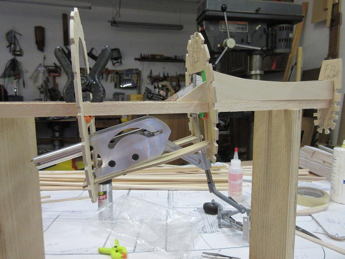
Up position:
Tail gear.
Darrell's tail gear is mounted horizontally, versus robart's vertically mounted. A ply plate was made to span F-10 to F-11. The F-10A former is for mounting robarts so that will be eliminated. All 1/8" thick aircraft ply. Slots cut into the two formers so the ply gear mount slides into each former by a 1/4", insuring no breaking due to glue failure.
There are six #6 screws holding the gear to the ply plate. An access hatch will be made on the bottom of the fuse so the screws can be secured while the gear is slide onto the top of the plate. I'll have to insure the tail doors are large enough for gear removal. They may have to be larger than scale (being Darrell's gear is a lot beefier), but, being on the bottom, a non noticeable feature.
Down position:
Dry fitted.
The horizontal stab incidence also dry fitted to insure clearance.
As with my 110" P-47, I plan on mounting the servo directly to the tail gear (hopefully, enough room to clear the stab).
Up position:
Last edited by samparfitt; 06-25-2015 at 04:52 PM.
06-27-2015, 07:45 AM
#13
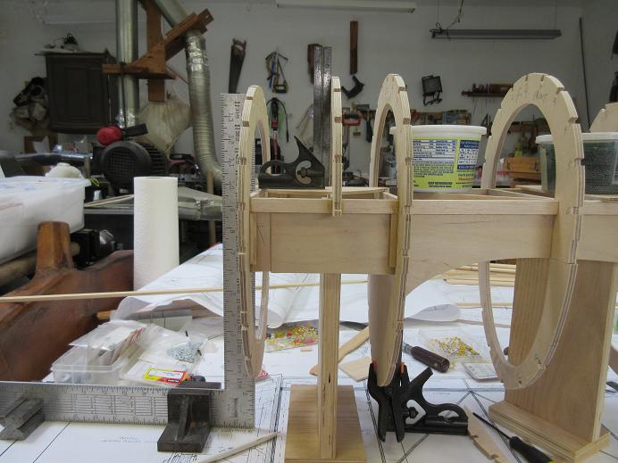
Formers:
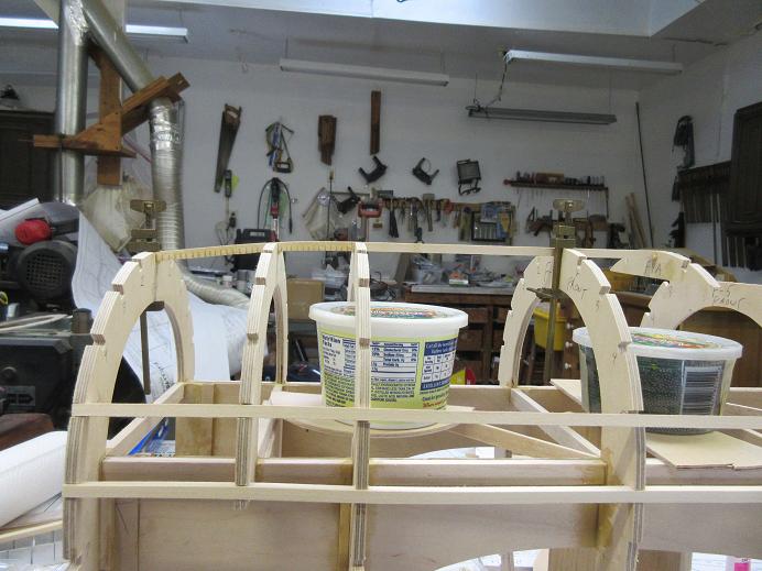
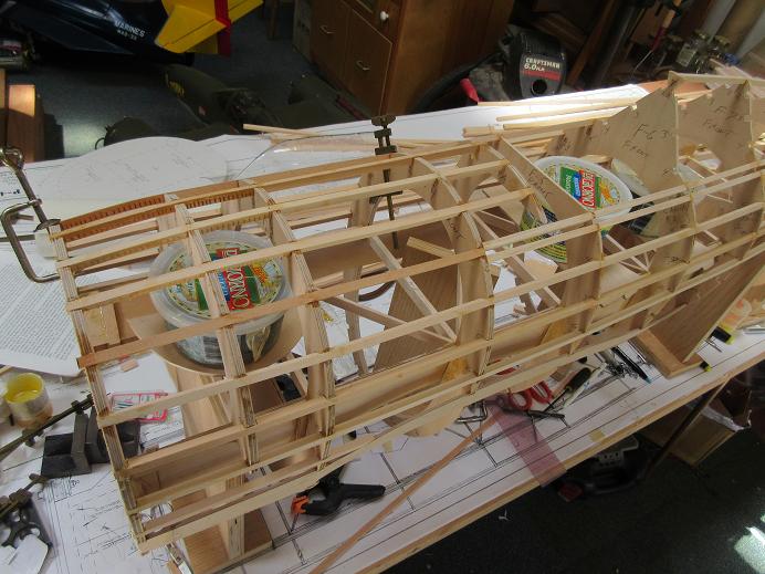
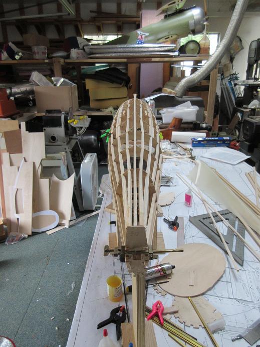
Put some butter containers with about 5 lbs of lead in each containers along the crutch to insure it stays straight.
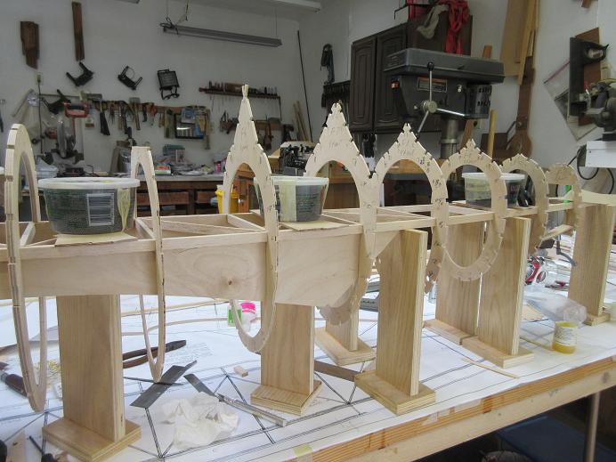
Started epoxying the formers to the crutch, 3 formers at a time.
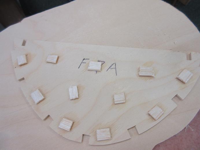
CA'ed some 3/32" thick balsa pieces as spacers between F-3 and F-3A for the belly pan.
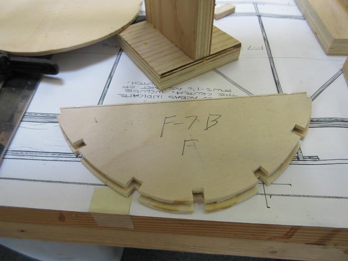
Did same for F-7A and F-7B for the back of the belly pan. These go at about a 45 degree angle so the edges were sanded appropriately for alignment.
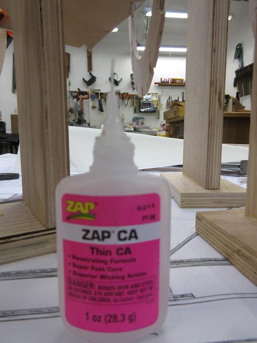
Nice tip I got from my buddy Scott:
After using the thin CA, hold vertical and squeeze the bottle to push out any liquid in the thin applicator to keep any CA from hardening in the thin applicator.
Put some butter containers with about 5 lbs of lead in each containers along the crutch to insure it stays straight.
Started epoxying the formers to the crutch, 3 formers at a time.
CA'ed some 3/32" thick balsa pieces as spacers between F-3 and F-3A for the belly pan.
Did same for F-7A and F-7B for the back of the belly pan. These go at about a 45 degree angle so the edges were sanded appropriately for alignment.
Nice tip I got from my buddy Scott:
After using the thin CA, hold vertical and squeeze the bottle to push out any liquid in the thin applicator to keep any CA from hardening in the thin applicator.
Last edited by samparfitt; 06-27-2015 at 07:54 AM.
06-27-2015, 01:22 PM
#14
Fuse (cont)
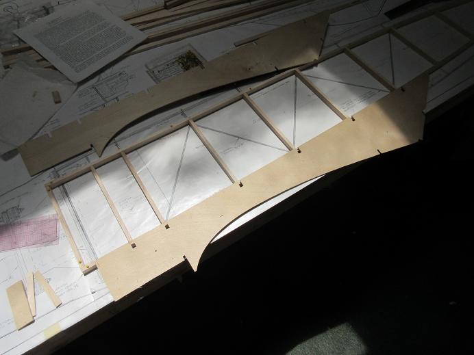
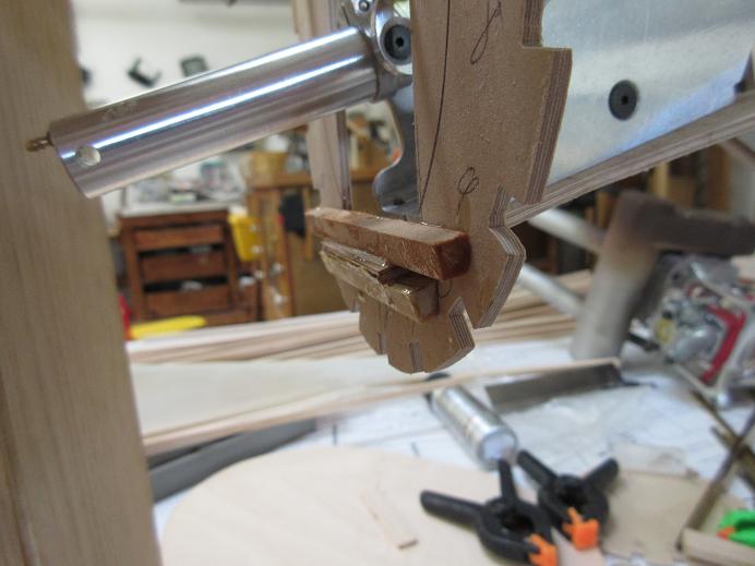
Stab saddle SS-1 and former F-12 epoxied to the crutch. Best to install SS-1's first as that dictates the exact position of F-11 to insure adequate room for the stab.
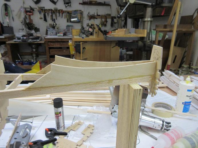
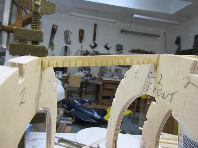
Top front stringer added along with F-4A. Inside of stringer gets multiple cuts to allow for curve of the fuse. All front stringers are basswood: insures a sturdy front for engine vibration/strength and is forward of the CG (so useful weight). Also, why the first 4 formers are 1/4" thick baltic ply.
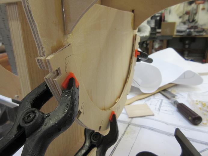
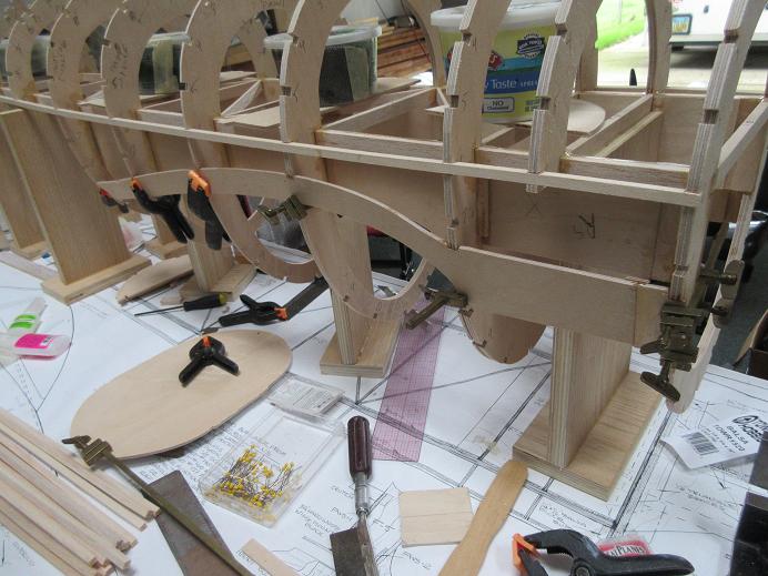
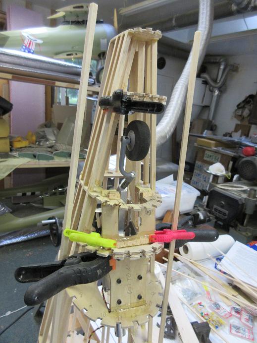
Outer wing saddles (FSW-2).
Lots of clamps to hold them in place as the ply bends around a lot of curves. Both sides done in unison, as well as stringers, to insure no warping of the fuse. Cuts were, prior to installing, made in the formers where the wing will be, save a short piece left uncut, to make removal of belly pan formers and waste where the wing will be located, easier to remove. Wing saddles adjustment (ie trimming) made at the top of the saddle as the bottom is where the wing will be located and needs to be accurately located along the cuts in the formers.
I forgot to also make the FSW-2 saddles an inch longer and, like the FSW-1's, had to sister on another inch of ply to the front.
Stab saddle SS-1 and former F-12 epoxied to the crutch. Best to install SS-1's first as that dictates the exact position of F-11 to insure adequate room for the stab.
Top front stringer added along with F-4A. Inside of stringer gets multiple cuts to allow for curve of the fuse. All front stringers are basswood: insures a sturdy front for engine vibration/strength and is forward of the CG (so useful weight). Also, why the first 4 formers are 1/4" thick baltic ply.
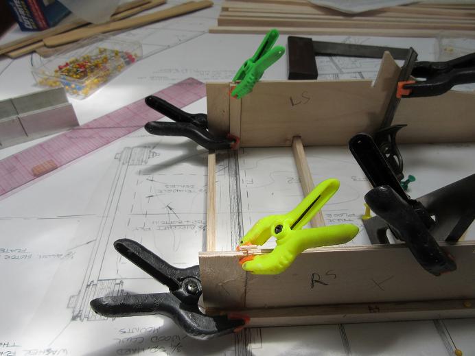
Outer wing saddles (FSW-2).
Lots of clamps to hold them in place as the ply bends around a lot of curves. Both sides done in unison, as well as stringers, to insure no warping of the fuse. Cuts were, prior to installing, made in the formers where the wing will be, save a short piece left uncut, to make removal of belly pan formers and waste where the wing will be located, easier to remove. Wing saddles adjustment (ie trimming) made at the top of the saddle as the bottom is where the wing will be located and needs to be accurately located along the cuts in the formers.
I forgot to also make the FSW-2 saddles an inch longer and, like the FSW-1's, had to sister on another inch of ply to the front.
Last edited by samparfitt; 06-27-2015 at 01:35 PM.
06-28-2015, 08:22 AM
#15
Fuse (cont)
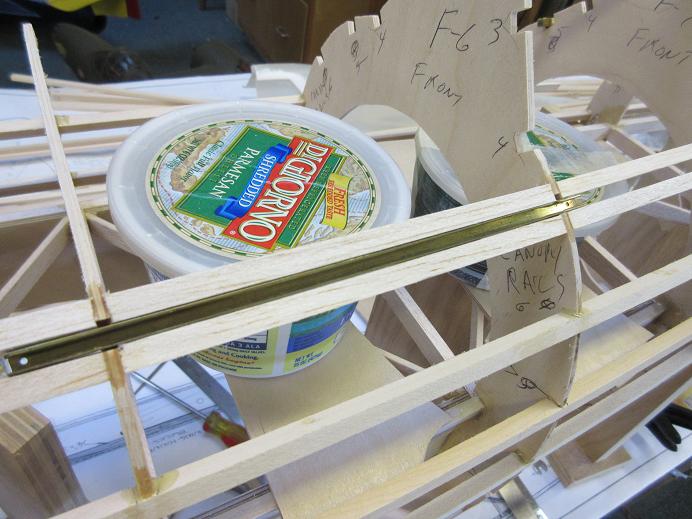
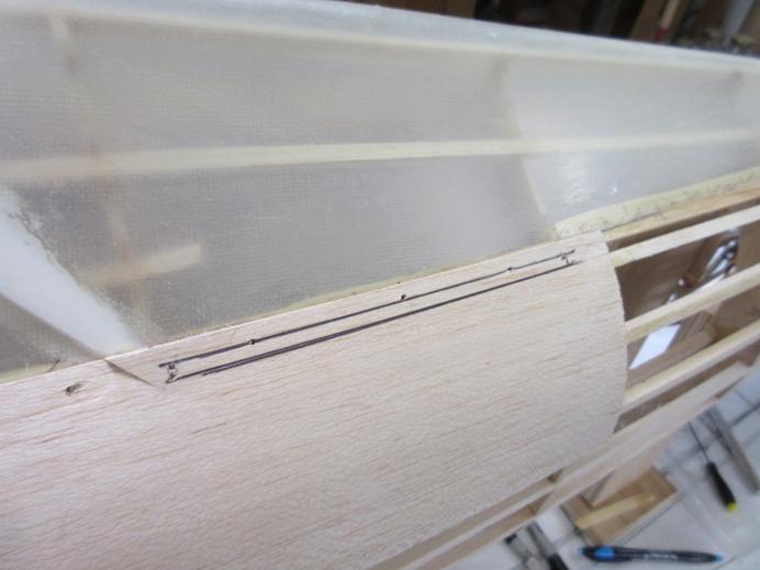
Prep for sliding canopy:
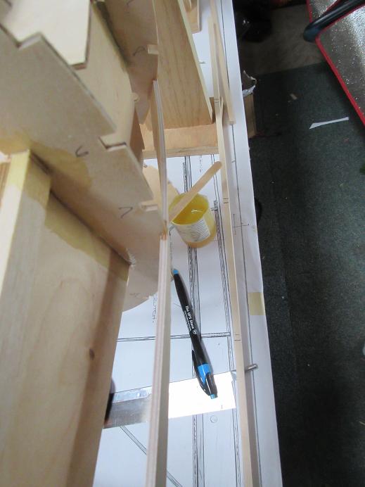
Some 1/4" square balsa was CA'ed around the 3/16" square brass tubing for the front and back attachments to the canopy. After sheeting the fuse, it will be easy to located, cut and sand the slots for the brass guides.
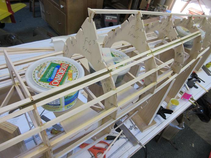
Top front of fuse stringers done:
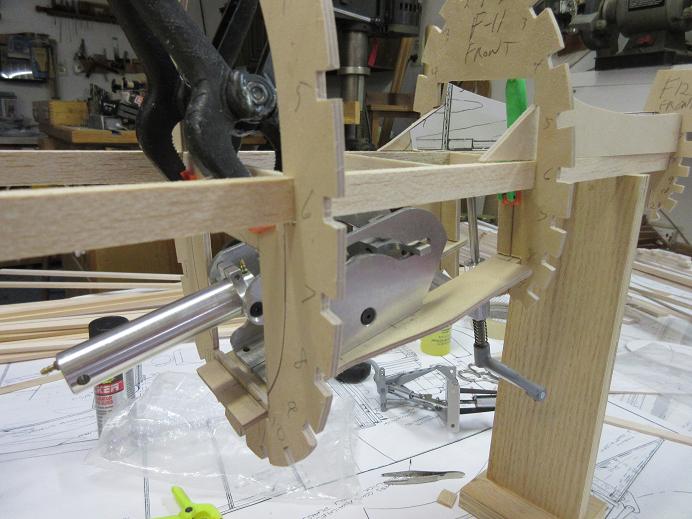
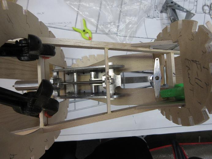
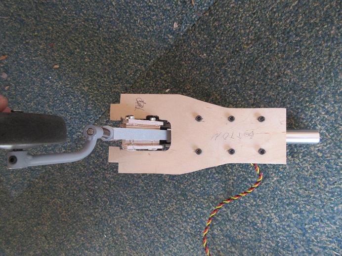
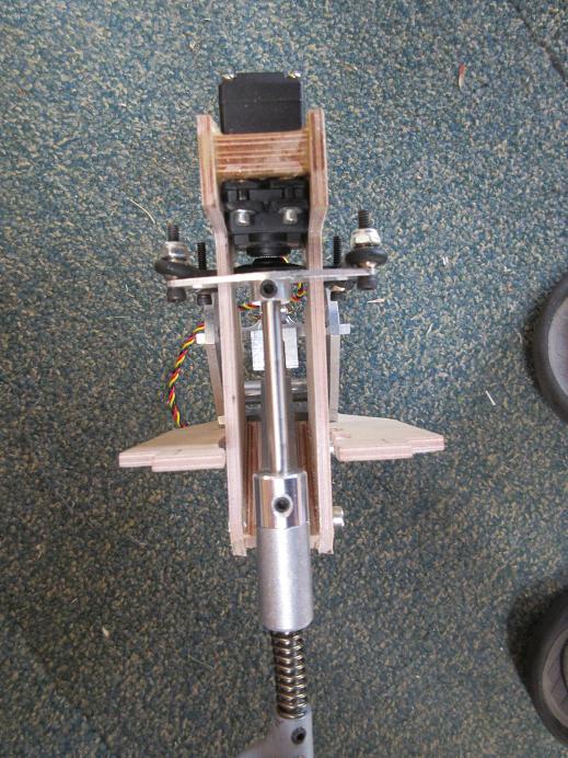
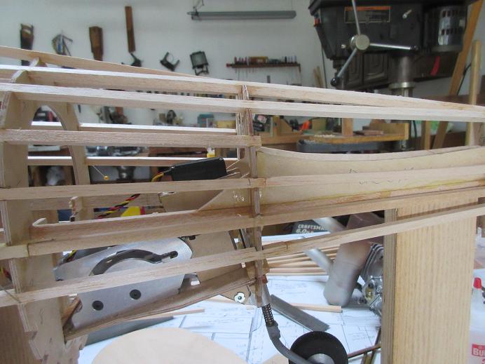
Tail gear direct mount servo and linkage.
An HS-645 with dubro 4/40 ball links used to control the steering.
1/8" thick aircraft ply used for the sides, and 3/32" thick glued up 3 layers per side to get 3/4" wide spacing from tail strut to servo. Some #6 screws used after drilling/tapping into the tail wheel strut.
Prep for sliding canopy:
Some 1/4" square balsa was CA'ed around the 3/16" square brass tubing for the front and back attachments to the canopy. After sheeting the fuse, it will be easy to located, cut and sand the slots for the brass guides.
Top front of fuse stringers done:
Tail gear direct mount servo and linkage.
An HS-645 with dubro 4/40 ball links used to control the steering.
1/8" thick aircraft ply used for the sides, and 3/32" thick glued up 3 layers per side to get 3/4" wide spacing from tail strut to servo. Some #6 screws used after drilling/tapping into the tail wheel strut.
Last edited by samparfitt; 06-28-2015 at 08:31 AM.
06-28-2015, 01:09 PM
#17
Fuse (cont)
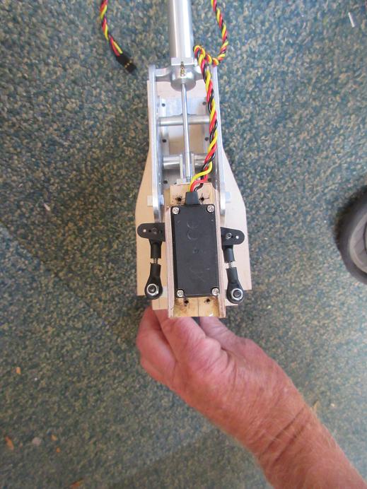
Tail gear (cont)
During the dry fit, some extra trimming had to be done to former F-11 and the gear mount so the tail gear could be removed from it's mount.
Some extra basswood for re-enforcement while installing the tail gear mount to the two formers F-10/11.
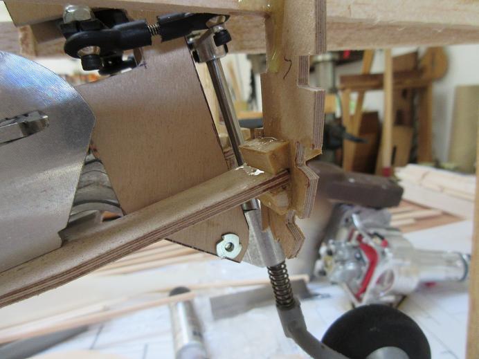
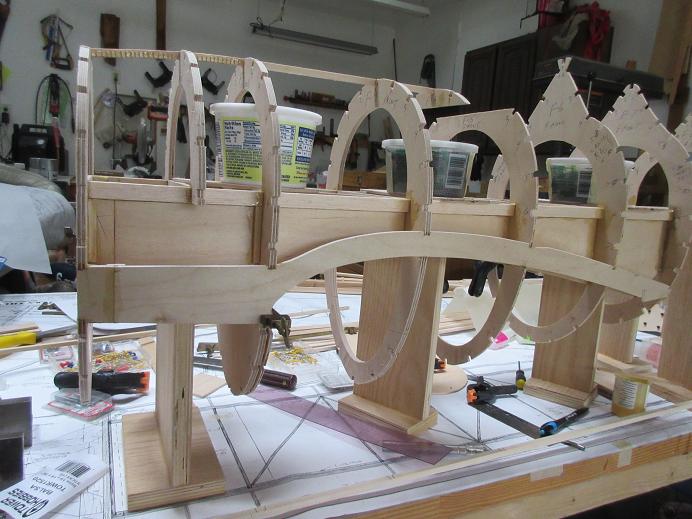
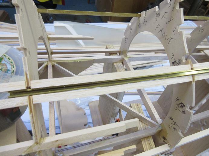
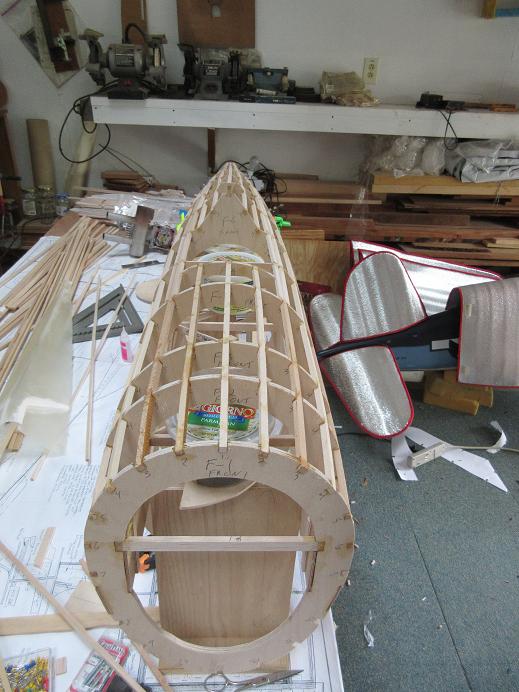
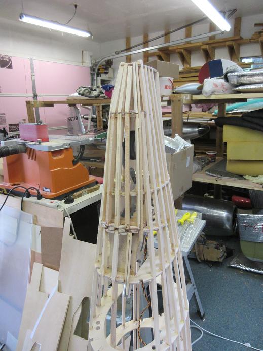
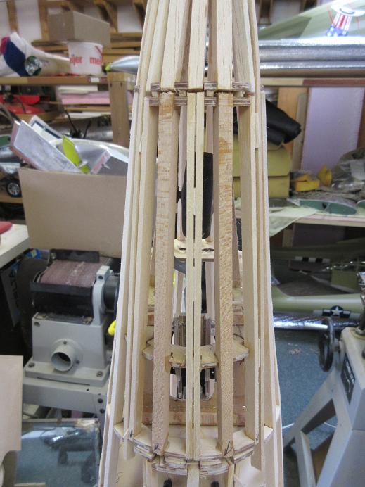
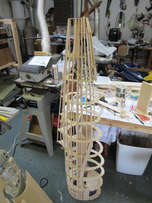
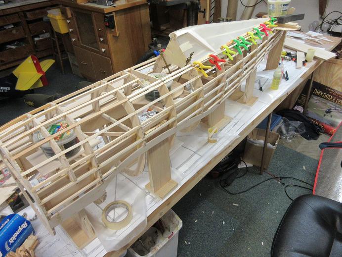
Stringers:
The top half is 'stringered'.
Tail gear (cont)
During the dry fit, some extra trimming had to be done to former F-11 and the gear mount so the tail gear could be removed from it's mount.
Some extra basswood for re-enforcement while installing the tail gear mount to the two formers F-10/11.
Stringers:
The top half is 'stringered'.
 06-29-2015, 08:23 AM
#19
Member
Join Date: Jun 2006
Location: CAMBRIDGE, UNITED KINGDOM
Posts: 36
Likes: 0
Received 0 Likes
on
0 Posts
Hi Sam ,
Following with interest ,as soon as my new shop is finished ,i'm building one !!
Aren't you worried about the extra weight in the tail , with the servo all the way back there ?
Or , is your 1" extension , taking care of that ??
Great work ,btw
Cheers
Phil
Following with interest ,as soon as my new shop is finished ,i'm building one !!
Aren't you worried about the extra weight in the tail , with the servo all the way back there ?
Or , is your 1" extension , taking care of that ??
Great work ,btw
Cheers
Phil
06-29-2015, 08:50 AM
#20
Phil,
That's why I add the 1 inch extension to the nose. I like short linkages so all servos are, usually, within a 3-6" of the moving surface.
With full cockpit, functioning cowl flaps and canopy, full doors that she will weigh 38-42 lbs. No problem with this size plane, especially with a DA-85 on the business end. I like planes that aren't bothered by cross winds and, when they land, they stay on the ground, and don't float back into the air. The P-47 can take the weight: with a huge wing and barn like flaps, it's an easy plane to fly and land.
==================
Fuse (cont)
Tail wheel doors:
Had to add F-10A half former as I forgot about the tail wheel doors. Also, had to make another former between F-11 and F-12 for the back of the doors. I took F-11 and F-12's template and made one about 1/2 the size between the two formers. Also, cut door end formers and CA'ed them to the fuse formers with some 2/32" thick balsa for spacers. Used all basswood so the doors would be sturdy as well as the door wells. The door frames and door well is made using 1/8"X1/4" basswood.
Also, made a hatch for accessing removing the 6 bolts holding the tail gear to the wood mount.
The door frames made before sheeting makes for easy cutting of the doors with no addition work to be done, save hinging.
I left the gear inside the fuse to insure, while making the door frames, that the gear would clear the doors.
Some 100 grit sandpaper wrapped around a paint stick used to smooth out all the stringers and formers.
Last edited by samparfitt; 06-29-2015 at 09:15 AM.
06-29-2015, 12:58 PM
#21
Fuse (cont)
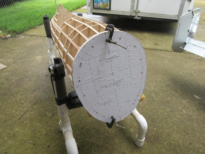
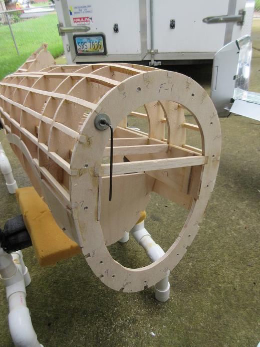
Fire wall:
Located about 12 locations on the removable fire wall, allowing for engine and muffler, and drilled holes for #6 bolts.
Clamped the FW to the fuse and drilled through the fixed FW. The fixed FW holes were then drilled out to 3/16" for blind nuts, some epoxy and each blind nut was driven home with an allen wrench.
Sheeting the fuse.
Put the fuse back on it's risers and weighted down.
1/8" thick balsa will be used.
Forgot that Nick sells a FG razor back turtle deck. Cleaned up any release agent on the FG part with alcohol and epoxied it to the fuse.
Last edited by samparfitt; 06-29-2015 at 01:01 PM.
06-29-2015, 03:00 PM
#22
Fuse (cont)
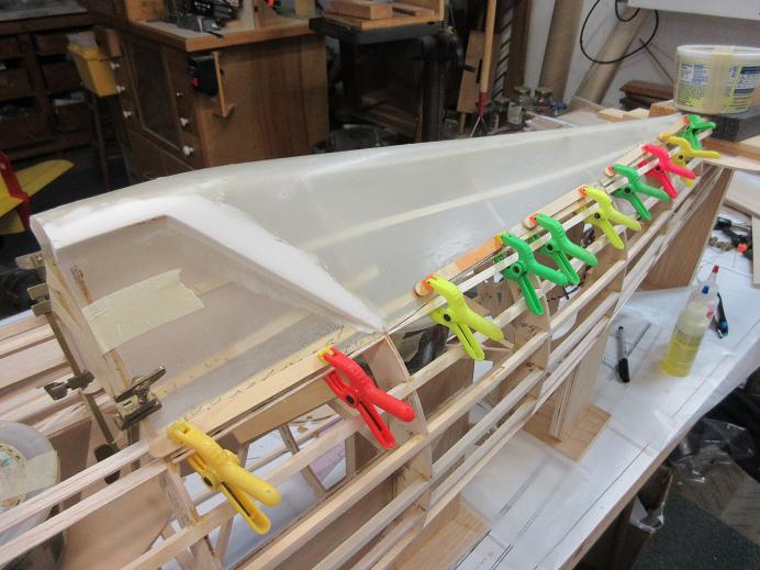
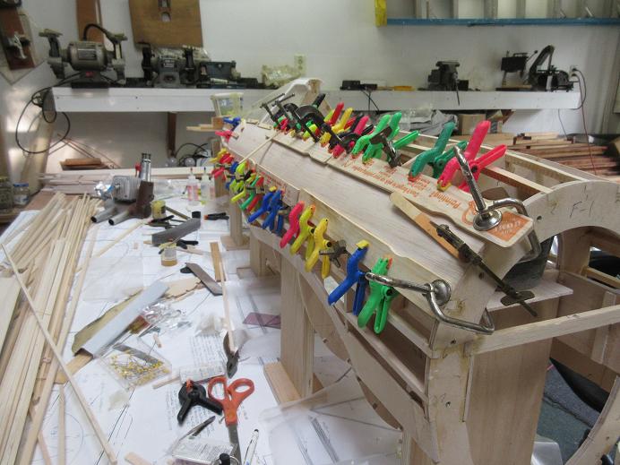
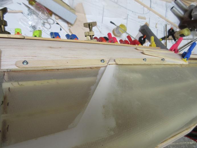
Planking:
The first 4" wide by 36" long piece glued on. Elmer's wood glue save where the sheeting overlapped the FG turtledeck was epoxy.
Some warm water over the exterior surface aided in the bend. Just about every clamp I had plus some servo screws to hold the planking over the FG where no clamps would reach.
06-29-2015, 03:01 PM
#23
Fuse (cont)
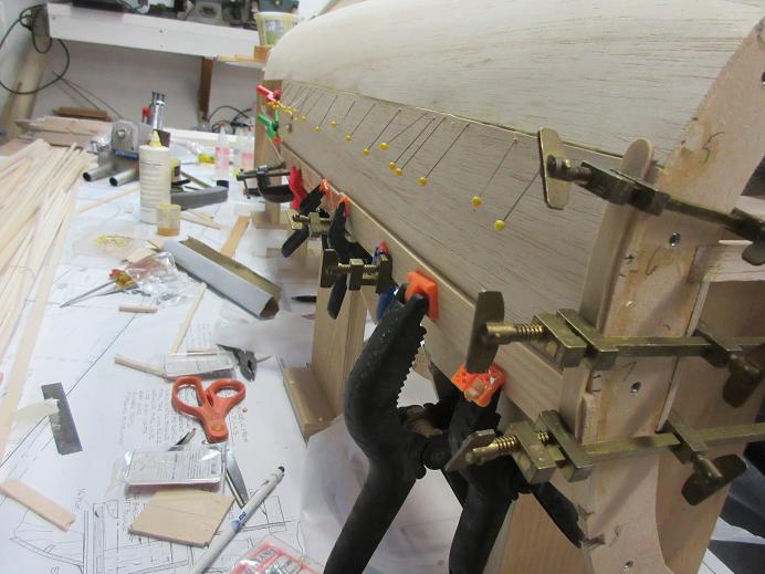
Planking:
The first 4" wide by 36" long piece glued on. Elmer's wood glue save where the sheeting overlapped the FG turtledeck was epoxy.
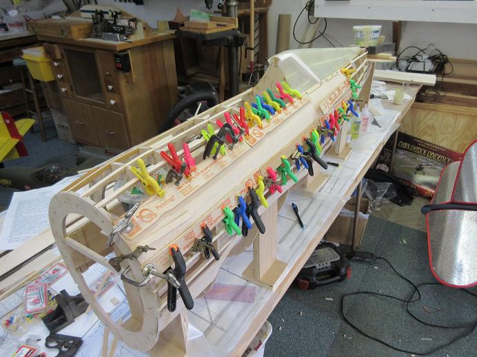
Some warm water over the exterior surface aided in the bend. Just about every clamp I had plus some servo screws to hold the planking over the FG where no clamps would reach. With the help of paint sticks, some C clamps needed to pull the edges down to the stringers and formers. Some brass bar clamps (5" and a foot long) also used to pull down the edges to the fuse. At the early stage, I can check inside to insure full contact with the fuse and sheeting, plus adding additional glue where needed.
Next, the opposite side will be done to insure no twisting or warping of the fuse frame.
The bottom stringers will be added later, permitting the fuse to rest on the risers and be weighted down during planking to insure no fuse warping. The risers also makes it easier to add the planking.
Planking:
The first 4" wide by 36" long piece glued on. Elmer's wood glue save where the sheeting overlapped the FG turtledeck was epoxy.
Some warm water over the exterior surface aided in the bend. Just about every clamp I had plus some servo screws to hold the planking over the FG where no clamps would reach. With the help of paint sticks, some C clamps needed to pull the edges down to the stringers and formers. Some brass bar clamps (5" and a foot long) also used to pull down the edges to the fuse. At the early stage, I can check inside to insure full contact with the fuse and sheeting, plus adding additional glue where needed.
Next, the opposite side will be done to insure no twisting or warping of the fuse frame.
The bottom stringers will be added later, permitting the fuse to rest on the risers and be weighted down during planking to insure no fuse warping. The risers also makes it easier to add the planking.
Last edited by samparfitt; 06-29-2015 at 03:09 PM.
06-30-2015, 05:27 AM
#24
Fuse (cont)
Planking (cont)
Clamps removed. Four holes drilled in the corners of where the sliding canopy brass guides are for future location, after glassing
Other 'mirror' side done.
Again, servo screws needed to secure planking to FG turtle deck.
The elmer's glue give me the needed time to secure the large piece of planking before the glue starts to set.
06-30-2015, 10:48 AM
#25
Fuse (cont)
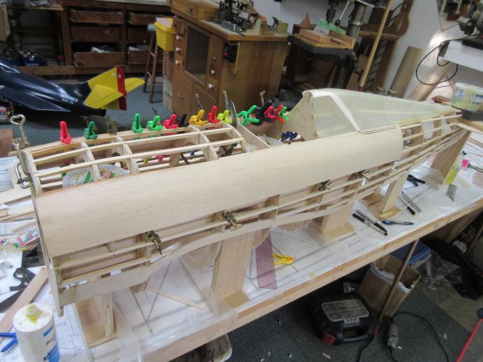
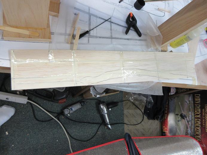
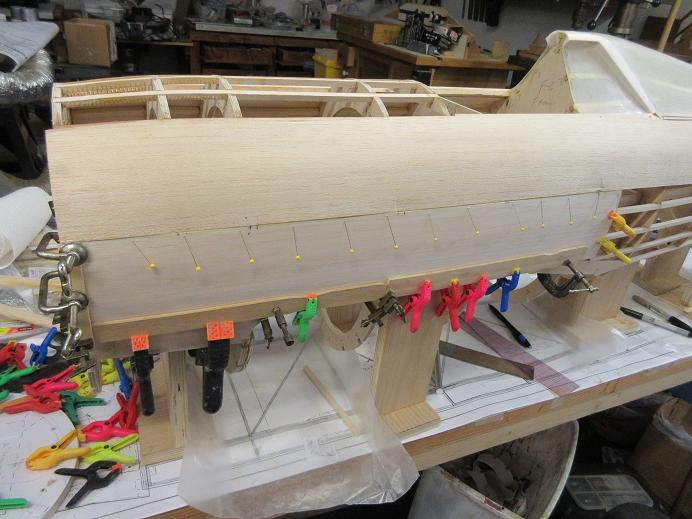
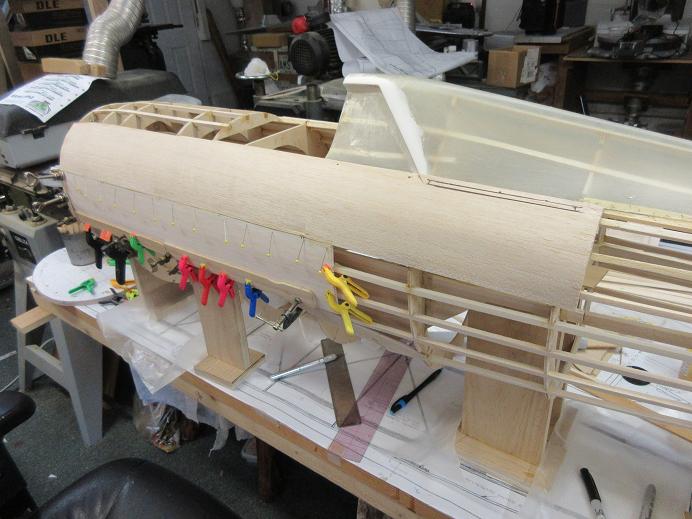
Planking (cont)
Second sheet down put on both sides.
I bevel the top/bottom edges to get a better fit of the two sheets.
The second sheet also cut several inches shorter to stagger the joints for strength.
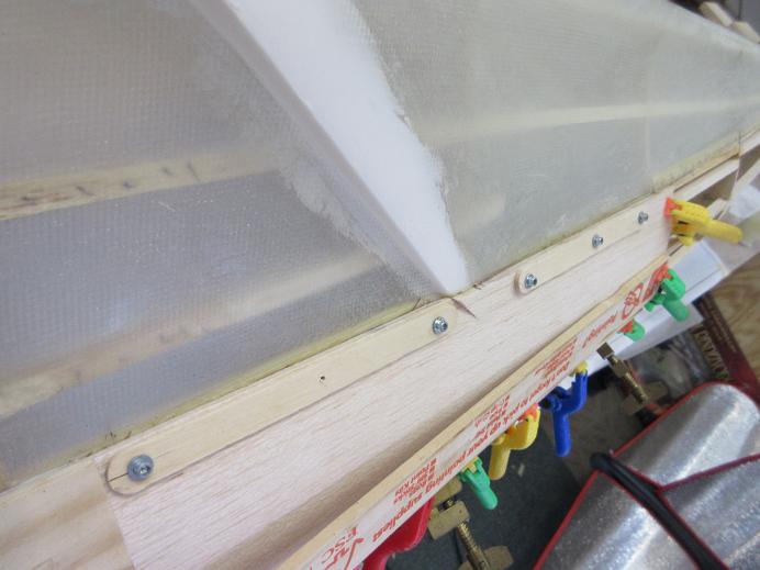
I trace the former and stringer locations on the back of the sheeting so both the sheeting and fuse get glue on their mating surfaces.
Some pins along the joining sheeting edges keeps the surfaces flush with each other. The severe angle of the pins into the adjoining sheeting keeps the sheeting flush. Too big of a curve and masking tape is needed. No water needed for these sheets as they only have a mild curve. The paint and popsicle sticks evenly distribute the pressure and also keep from marring the sheeting.
Planking (cont)
Second sheet down put on both sides.
I bevel the top/bottom edges to get a better fit of the two sheets.
The second sheet also cut several inches shorter to stagger the joints for strength.
I trace the former and stringer locations on the back of the sheeting so both the sheeting and fuse get glue on their mating surfaces.
Some pins along the joining sheeting edges keeps the surfaces flush with each other. The severe angle of the pins into the adjoining sheeting keeps the sheeting flush. Too big of a curve and masking tape is needed. No water needed for these sheets as they only have a mild curve. The paint and popsicle sticks evenly distribute the pressure and also keep from marring the sheeting.
Last edited by samparfitt; 06-30-2015 at 10:54 AM.