


Safety Starting Table Plans
 04-19-2023, 08:08 AM
#1
Senior Member
Thread Starter
Join Date: Feb 2023
Location: Corryton, TN. Fly at Lucky Lane RC Club
Posts: 164
Likes: 0
Received 24 Likes
on
22 Posts
Safety Starting Tables
I am presenting my design for a safety starting table for RC airplanes. I have addressed the problems I have observed with other starting table designs. Most tables are too narrow at the back end, don�t have enough space to work on the model, have no place to set the flight box/starter/battery, can sink into soft/muddy soils and are heavy to move for mowing. I built this table entirely out of recycled 2x6 pressure treated lumber I salvaged from a deck repair project. All fasteners are #10 deck screws, also recycled from the deck repair project. The protective padding on the uprights is made from a foam swim noodle. The front tray is 6 feet wide and 12 inches deep which allows plenty of room to set a starting caddy, fuel can and transmitter. The legs are screwed onto base plates to prevent sinking into the ground. The table can be tipped up onto the uprights and the front tray to allow easy mowing under the table. The table area is large enough to allow ample room for tools and parts while working on the model.
Construction:
The plans identify each piece by a letter, list the length (in inches) and how many are required. All wood is pressure treated 2x6 lumber. Start by cutting four boards each 6 feet long (72�). Lay two boards on the floor in a �V� pattern and lay the other two boards across the �V� to form the front platform area. The rear end should have the boards 5.5� apart as measured on the outside edges to match the width of the 2x6 rear leg that will be attached later. Place the other two boards across the front end of the �V� and spread the �V open to have 25.5� of separation at inside edges at the rear of the front two boards. Screw these two boards onto the �V�. Now flip the assembly upside down and attach the rear leg (F) to the ends of the �V� frame. Now cut three part B pieces to 48� in length. Mark two of them at 28.5�. Turn the assembly up on edge and attach the legs using the 28.5� mark to ensure the front legs match the height of the real leg. Turn the assembly upside down and attach the front base plate (B) to the bottom the front legs. Attach the rear base plate (M) to the bottom of the rear leg. Attach brace support pad (L). Attach the cross braces C, D, and G. Turn table right side up and miter cut part H to fit between the leg uprights. Attach the platform pieces H, E, G, I, J and K. Draw a line across the ends of pieces G, I, J, K and saw off the irregular pieces to taper the rear of the platform. Round off all corners and then install the padding on the uprights. I used a swim noodle for the padding. Cut it to a length about an inch taller than the top of the uprights and then make a lengthwise cut to open it up like a �C� to clamp onto the upright and then tape it in place.
To make the ground contacting base plates last longer, coat them with two coats of Copper Naphthenate (available from Home Depot as Copper Green Wood Preservative 850604).
The table will be heavy, so get two of your friends to help you move the table to its desired location.
The attached photos should help with some of the construction details and also show how it can be tipped up for ease of mowing around/under it. I hope you enjoy using it as much as I have mine.
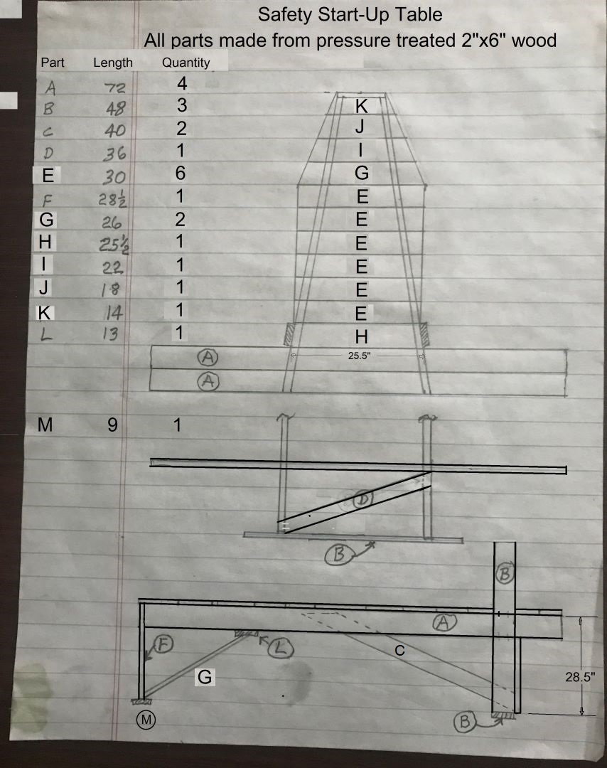
Plans
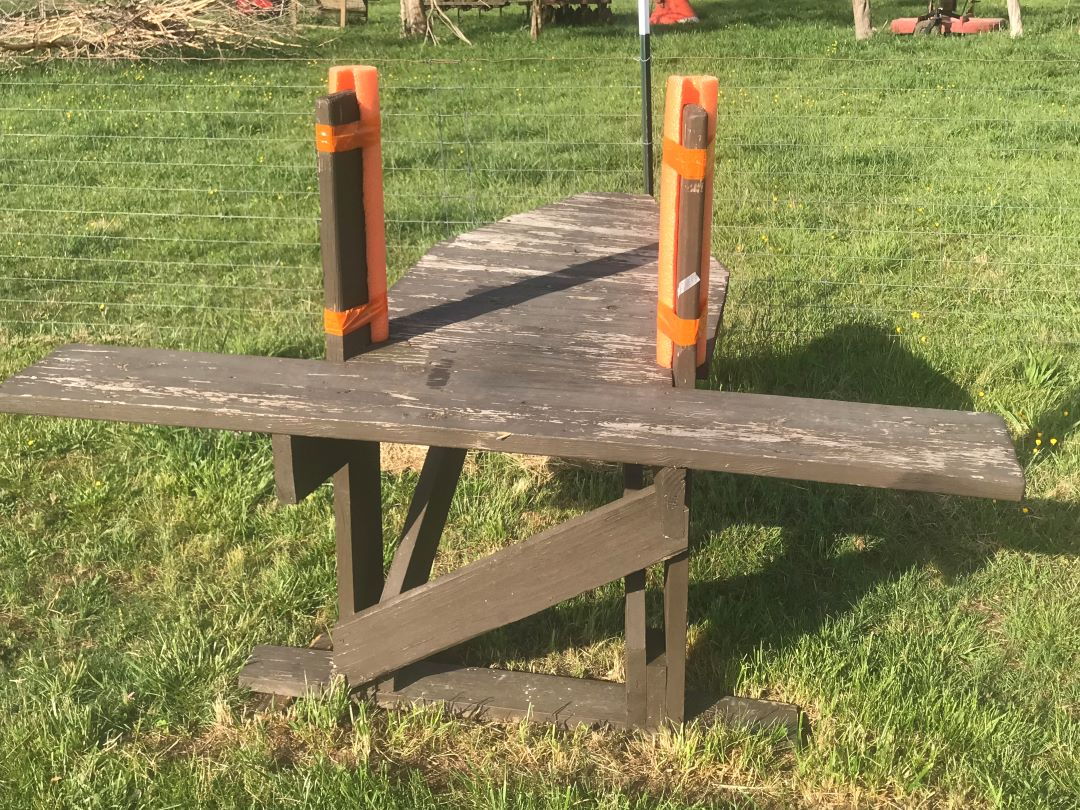
Front view
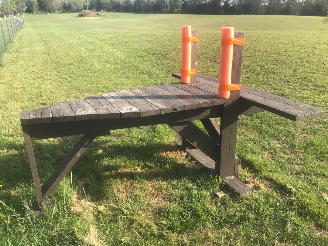
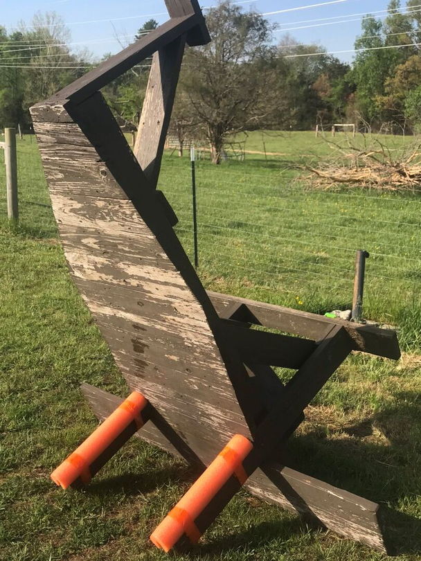
side view
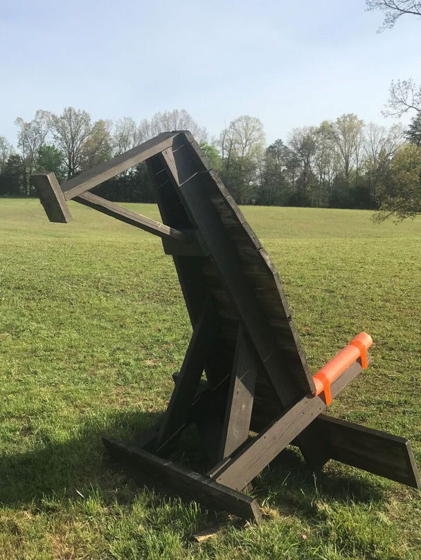
Tipped up half way
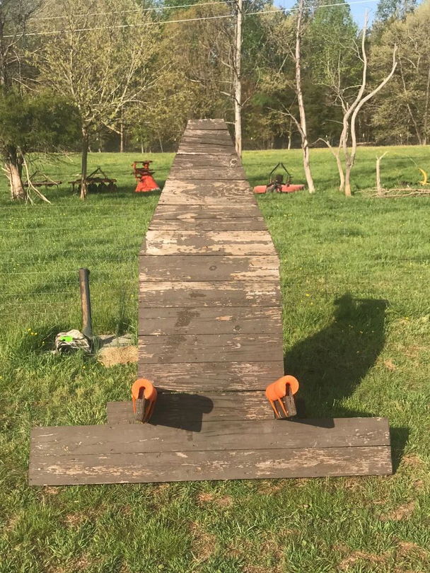
Top view
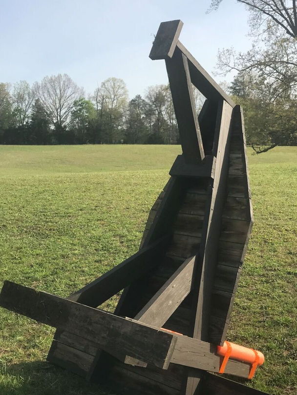
Tipped up all the way for mowing under it
Bottom side construction details
I am presenting my design for a safety starting table for RC airplanes. I have addressed the problems I have observed with other starting table designs. Most tables are too narrow at the back end, don�t have enough space to work on the model, have no place to set the flight box/starter/battery, can sink into soft/muddy soils and are heavy to move for mowing. I built this table entirely out of recycled 2x6 pressure treated lumber I salvaged from a deck repair project. All fasteners are #10 deck screws, also recycled from the deck repair project. The protective padding on the uprights is made from a foam swim noodle. The front tray is 6 feet wide and 12 inches deep which allows plenty of room to set a starting caddy, fuel can and transmitter. The legs are screwed onto base plates to prevent sinking into the ground. The table can be tipped up onto the uprights and the front tray to allow easy mowing under the table. The table area is large enough to allow ample room for tools and parts while working on the model.
Construction:
The plans identify each piece by a letter, list the length (in inches) and how many are required. All wood is pressure treated 2x6 lumber. Start by cutting four boards each 6 feet long (72�). Lay two boards on the floor in a �V� pattern and lay the other two boards across the �V� to form the front platform area. The rear end should have the boards 5.5� apart as measured on the outside edges to match the width of the 2x6 rear leg that will be attached later. Place the other two boards across the front end of the �V� and spread the �V open to have 25.5� of separation at inside edges at the rear of the front two boards. Screw these two boards onto the �V�. Now flip the assembly upside down and attach the rear leg (F) to the ends of the �V� frame. Now cut three part B pieces to 48� in length. Mark two of them at 28.5�. Turn the assembly up on edge and attach the legs using the 28.5� mark to ensure the front legs match the height of the real leg. Turn the assembly upside down and attach the front base plate (B) to the bottom the front legs. Attach the rear base plate (M) to the bottom of the rear leg. Attach brace support pad (L). Attach the cross braces C, D, and G. Turn table right side up and miter cut part H to fit between the leg uprights. Attach the platform pieces H, E, G, I, J and K. Draw a line across the ends of pieces G, I, J, K and saw off the irregular pieces to taper the rear of the platform. Round off all corners and then install the padding on the uprights. I used a swim noodle for the padding. Cut it to a length about an inch taller than the top of the uprights and then make a lengthwise cut to open it up like a �C� to clamp onto the upright and then tape it in place.
To make the ground contacting base plates last longer, coat them with two coats of Copper Naphthenate (available from Home Depot as Copper Green Wood Preservative 850604).
The table will be heavy, so get two of your friends to help you move the table to its desired location.
The attached photos should help with some of the construction details and also show how it can be tipped up for ease of mowing around/under it. I hope you enjoy using it as much as I have mine.
Plans
Front view
side view
Tipped up half way
Top view
Tipped up all the way for mowing under it
Bottom side construction details
Last edited by LLRCFlyer; 04-20-2023 at 04:40 AM. Reason: typos on plans
 04-19-2023, 12:33 PM
#2

I like the modifications to the traditional stand. Many clubs put wheels on the front to ease moving for lawn mowing. If done, a provision for staking down the rear leg should be made. My bigger planes have enough power to move the wheeled stand forward, even a lower throttle settings!
04-19-2023, 02:18 PM
#3
Senior Member
Thread Starter
Join Date: Feb 2023
Location: Corryton, TN. Fly at Lucky Lane RC Club
Posts: 164
Likes: 0
Received 24 Likes
on
22 Posts
Hi Ted,
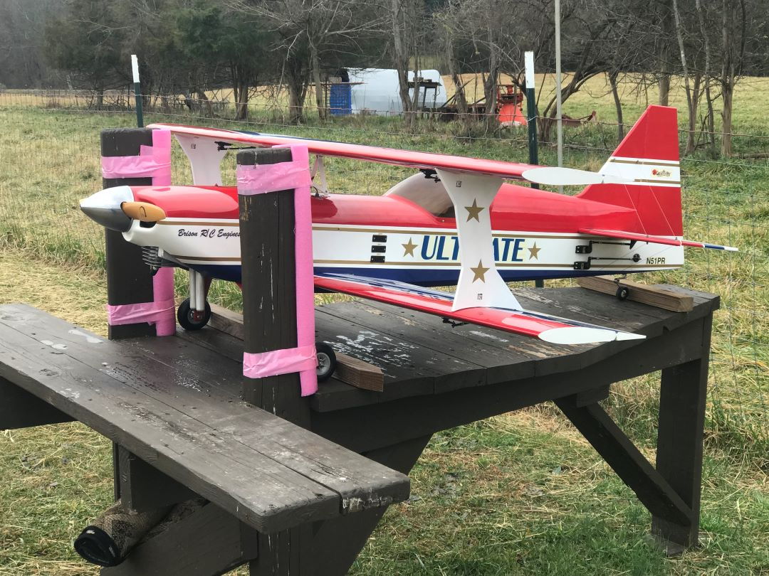
Yes, staking may be needed if wheels are used. That is why I didn't use them and devised the tip-up method instead to provide for mowing around the table. I just tried pulling on the uprights at about a foot above the table (a typical thrust line). My fish scale only reads to 50 pounds force and that was no where near enough to skid or tip the table. The table is heavy and needs three people to move it any distance. No model small enough to fit on the table will produce enough thrust to budge it. I have started my 55 cc gassers (including the Great Planes Ultimate Bipe shown on the table) with no problems. I do recommend using wheel chocks to prevent the model from rolling around on the table.

My 55 cc Ultimate Biplane on the table fits fine and has no where near enough thrust to scoot or tip the table. Rock solid support.
Yes, staking may be needed if wheels are used. That is why I didn't use them and devised the tip-up method instead to provide for mowing around the table. I just tried pulling on the uprights at about a foot above the table (a typical thrust line). My fish scale only reads to 50 pounds force and that was no where near enough to skid or tip the table. The table is heavy and needs three people to move it any distance. No model small enough to fit on the table will produce enough thrust to budge it. I have started my 55 cc gassers (including the Great Planes Ultimate Bipe shown on the table) with no problems. I do recommend using wheel chocks to prevent the model from rolling around on the table.
My 55 cc Ultimate Biplane on the table fits fine and has no where near enough thrust to scoot or tip the table. Rock solid support.
