


Road trips: 2024
 06-21-2024, 04:39 PM
#26

CY A6M Zero and Black Horse Gilmore racer (84.5")
========
I only did one item on the A6M zero.
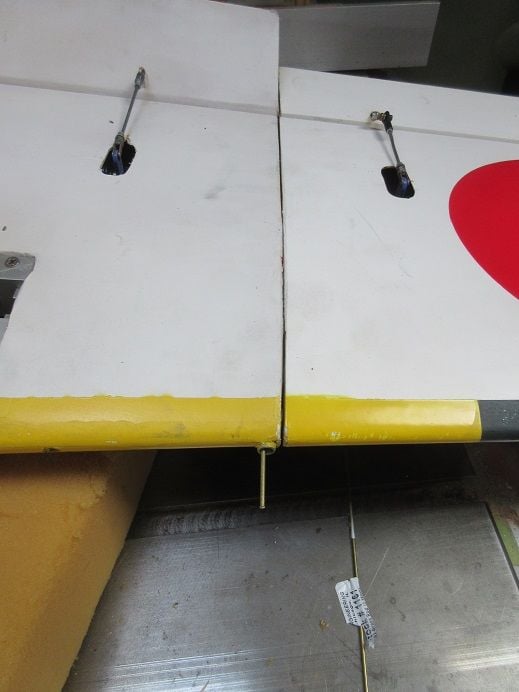
Cut some brass rod to secure the outer wings to the inner wings.
I'll, probably, glue a dowel rod and brass tube as a gun on the end of the rod.
Tom Shafer was 'kind enough' to inform me that my engine is a Fuji 86 CC engine.
=====================
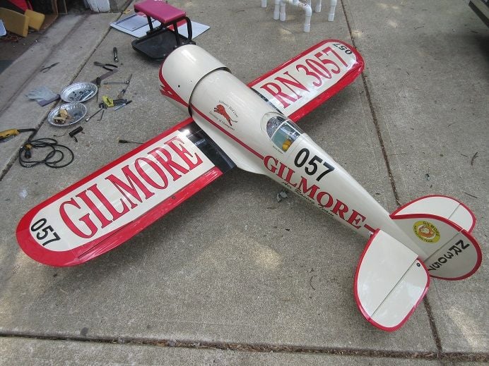
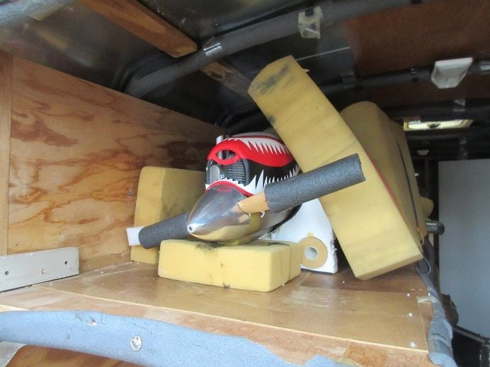
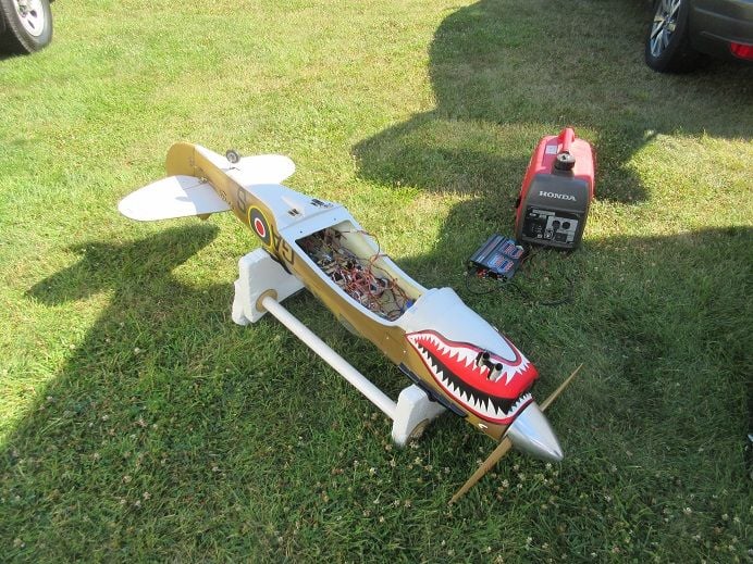
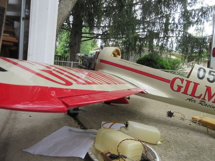
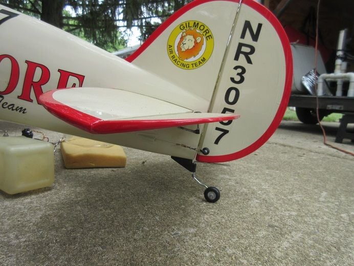
Black Horse Gilmore racer 84.5".
One more plane I acquired at last Fall's estate auction.
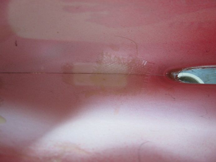
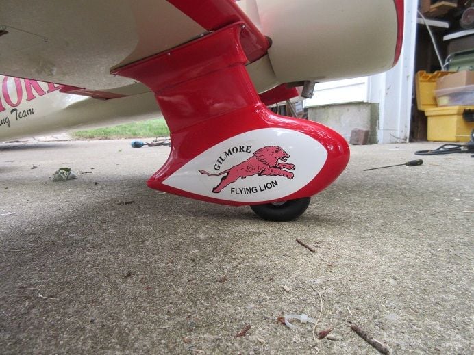
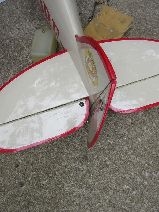
Epoxied and glassed the inside of one 'gear pant' that was 'splitting at the seams'.
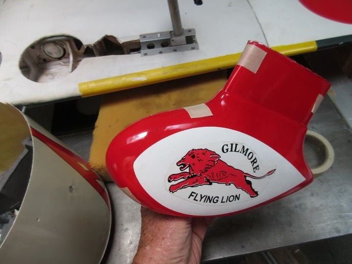
Inside view.
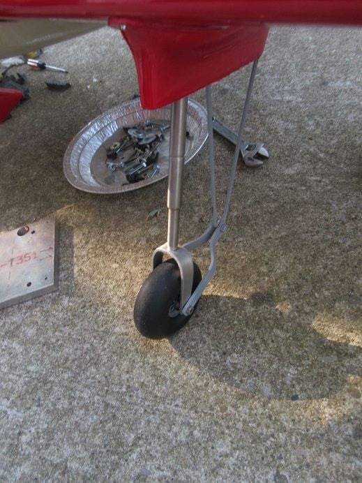
Nice main gear and not just a 'piece of wire'.
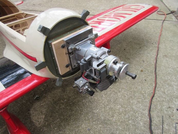
Installing a G-62 in this plane so:
Had some G-62's that got damaged last year due to a bad transmitter battery
Removed salvaged parts; ie carb, muffler, magneto and 'spring starter'.
Had to use some 'heat' to remove the spring starter 'center tube'.
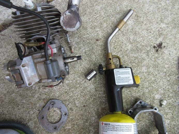
I think this may be beyond repair!!!
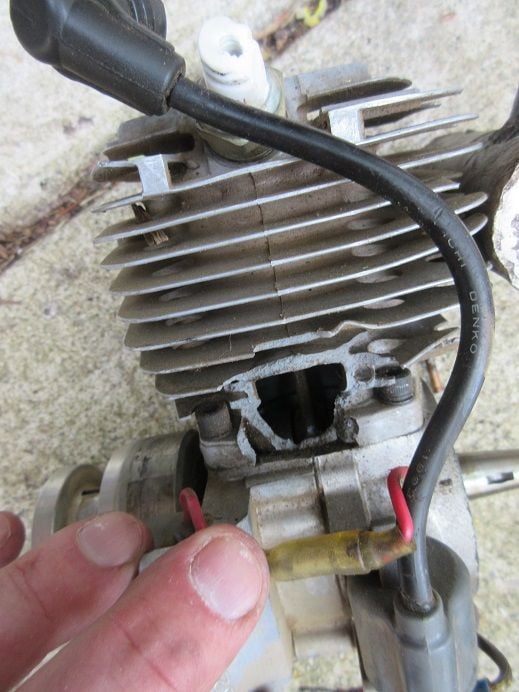
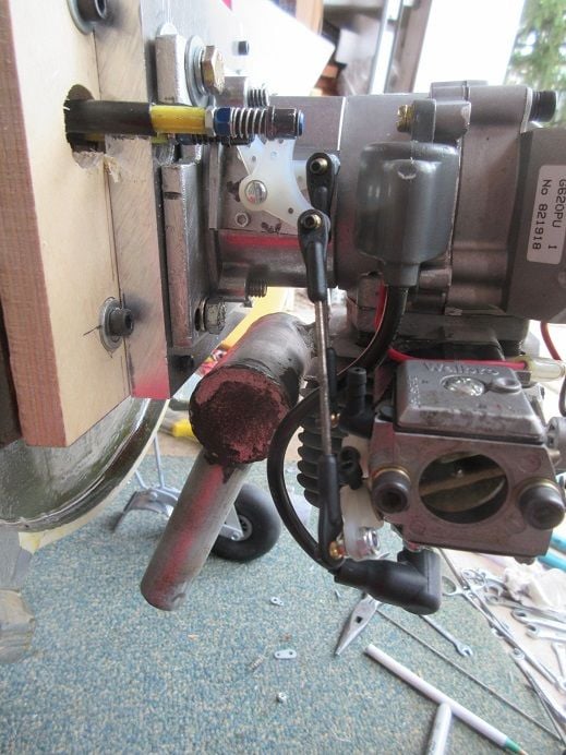
Another G-62 with electronic ignition that needed a carb spacer.
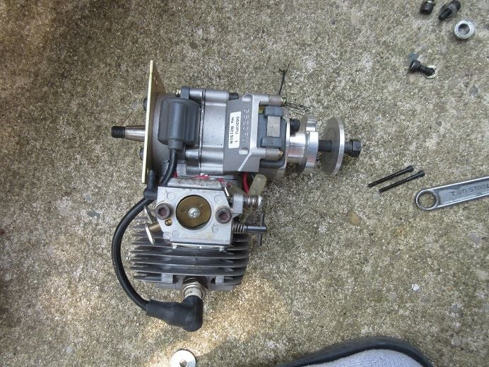
The other G-62 I got at the estate auction and just noticed that the engine is brand new and never used so using this one in the Gilmore.
I like magneto; no battery to 'worry about'!
I've got each and haven't noticed any difference in 'performance'.
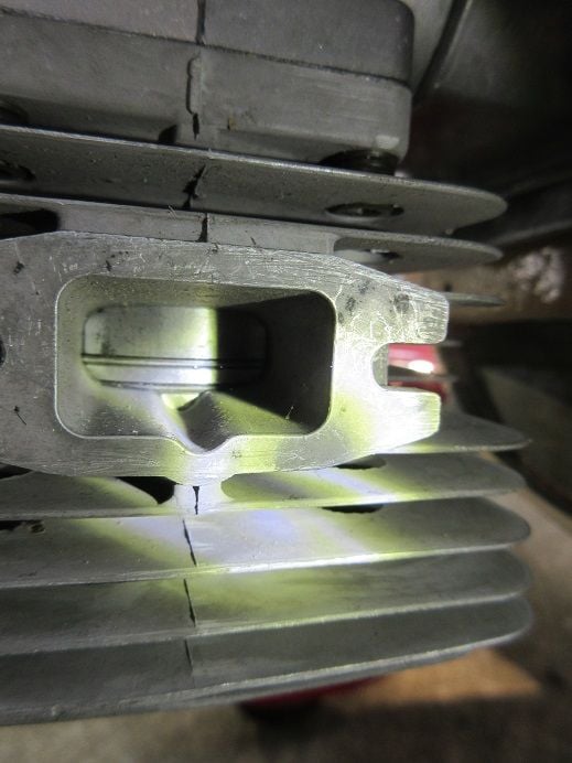
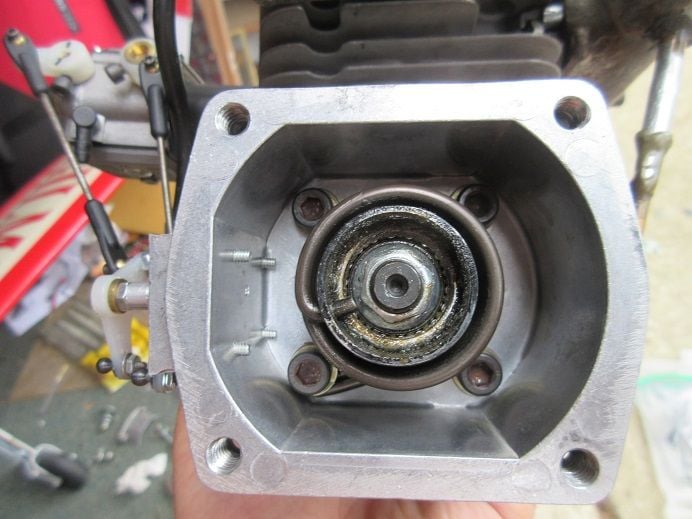
Inside of the cylinder head.
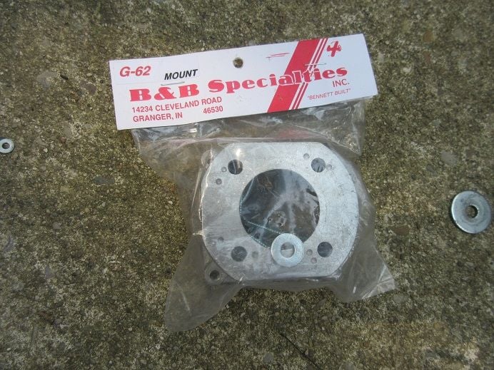
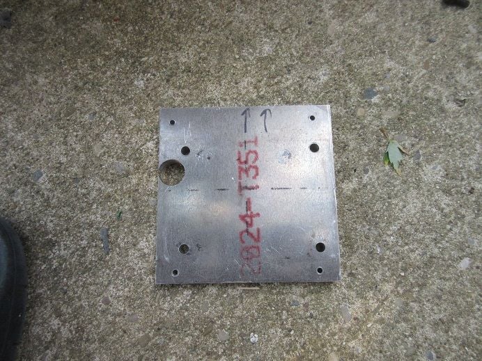
New engine mount plate.
Bought these about 10 years ago as 'spares'.
Spring starter added.
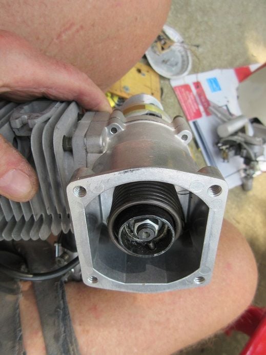
Metal back plate added.
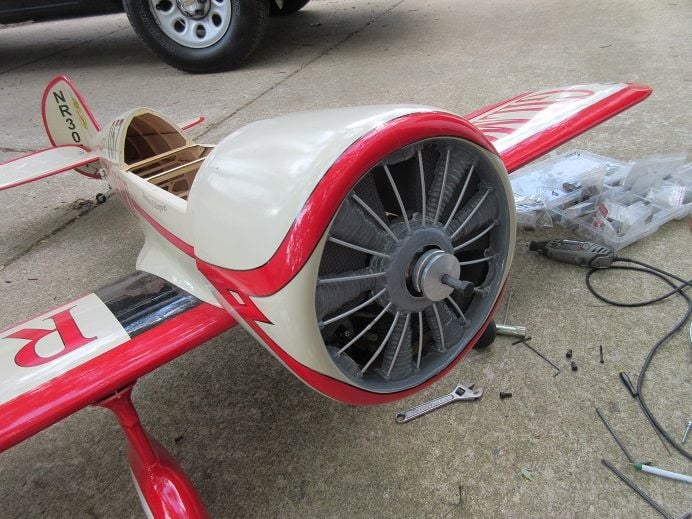
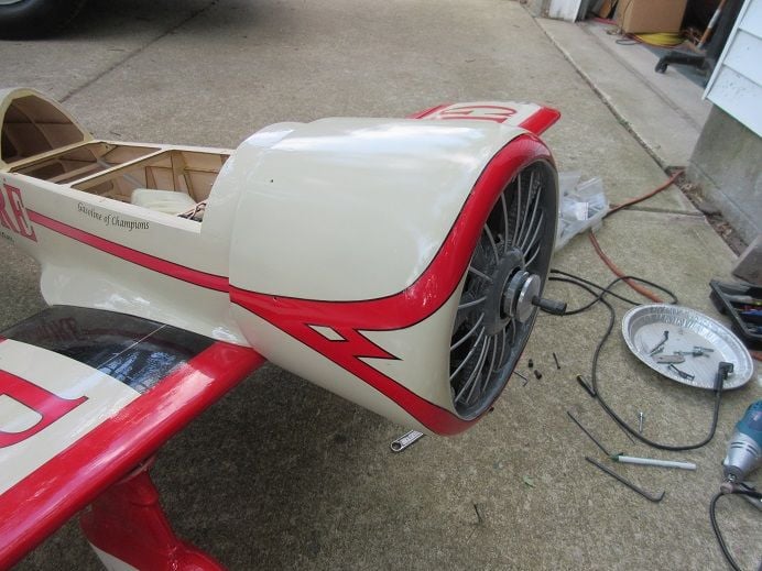
Going to need all the weight possible with such a short 'nose' on this plane.
Need 8" for the prop to clear the cowl so lots of 'fire wall'.
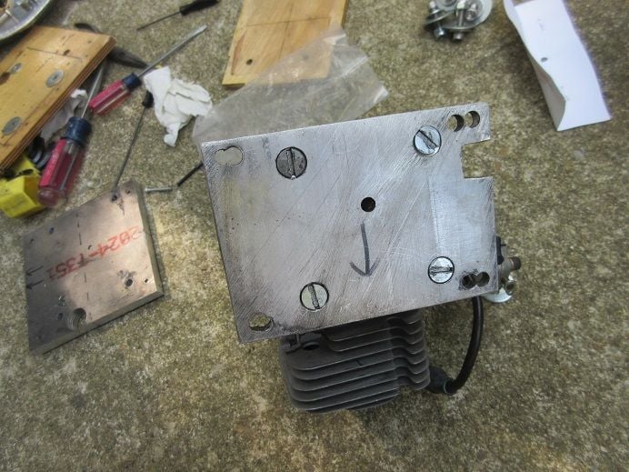
Cut and screwed a 1/2" thick multi-ply to the original fire wall.
The 2nd piece of fire wall is a 'template' to insure the engine is off set enough to be in the center of the front of the cowl.
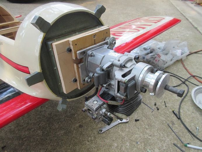
Will need a lot of 'washers' to have the correct 'off set'.
This metal plate will replace the 2nd wood template.
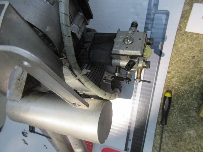
Here is the other electronic G-62 that I thought about using.
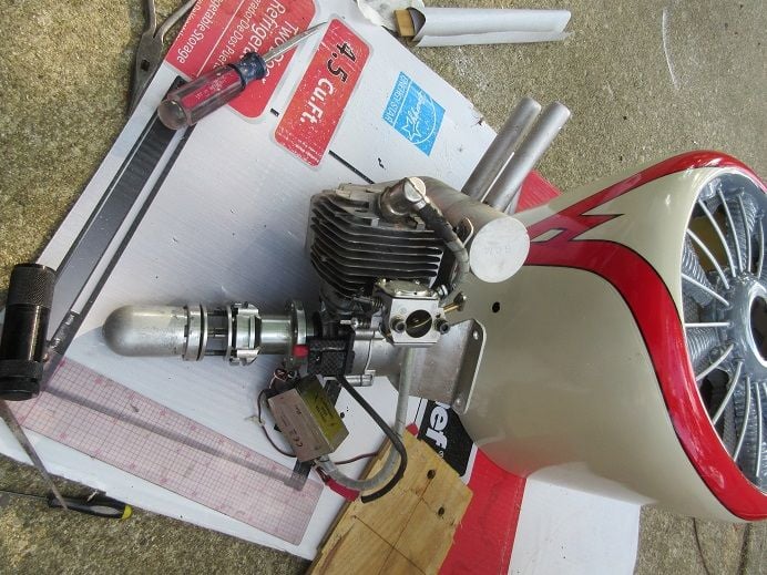
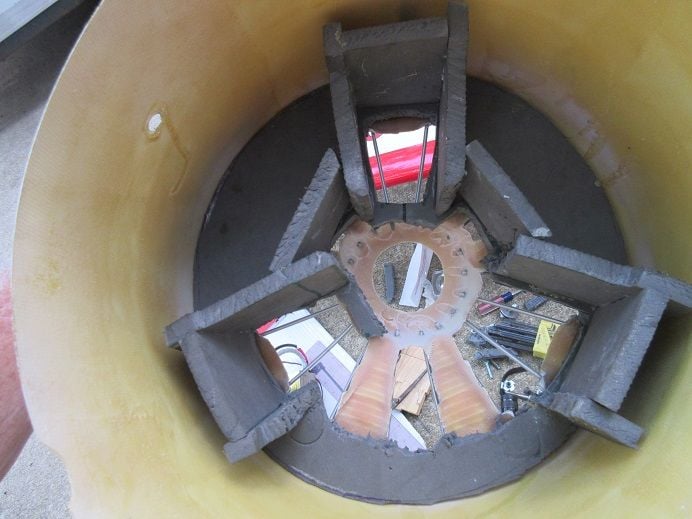
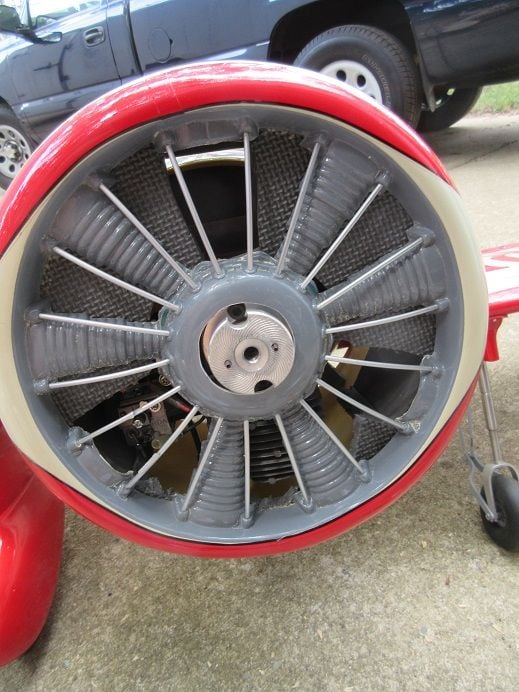
The inside of the cowl.
Guess the original owner was going to put a 3 cylinder engine in this plane.
I had to 'butcher it up' so the G-62 would 'fit'.
'Dry fit'.
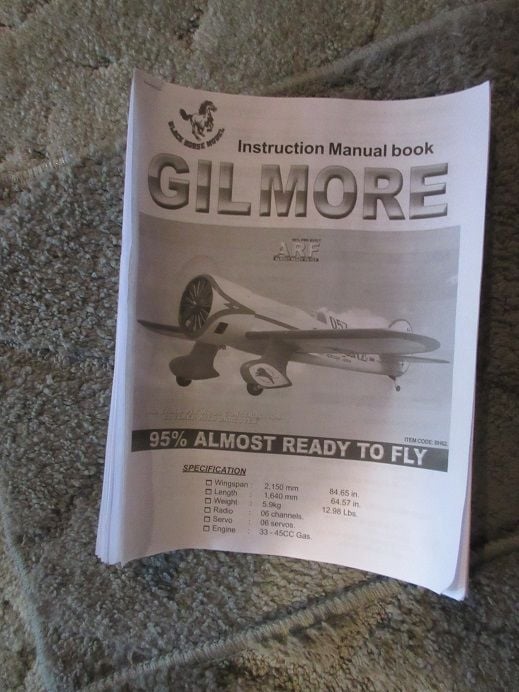
Guess I should read this!
===================
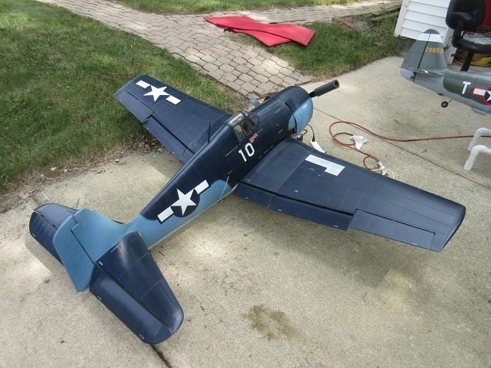
Also, charged the batteries in the Z F6F Hellcat.
========
I only did one item on the A6M zero.
Cut some brass rod to secure the outer wings to the inner wings.
I'll, probably, glue a dowel rod and brass tube as a gun on the end of the rod.
Tom Shafer was 'kind enough' to inform me that my engine is a Fuji 86 CC engine.
=====================
Black Horse Gilmore racer 84.5".
One more plane I acquired at last Fall's estate auction.
Epoxied and glassed the inside of one 'gear pant' that was 'splitting at the seams'.
Inside view.
Nice main gear and not just a 'piece of wire'.
Installing a G-62 in this plane so:
Had some G-62's that got damaged last year due to a bad transmitter battery
Removed salvaged parts; ie carb, muffler, magneto and 'spring starter'.
Had to use some 'heat' to remove the spring starter 'center tube'.
I think this may be beyond repair!!!
Another G-62 with electronic ignition that needed a carb spacer.
The other G-62 I got at the estate auction and just noticed that the engine is brand new and never used so using this one in the Gilmore.
I like magneto; no battery to 'worry about'!
I've got each and haven't noticed any difference in 'performance'.
Inside of the cylinder head.
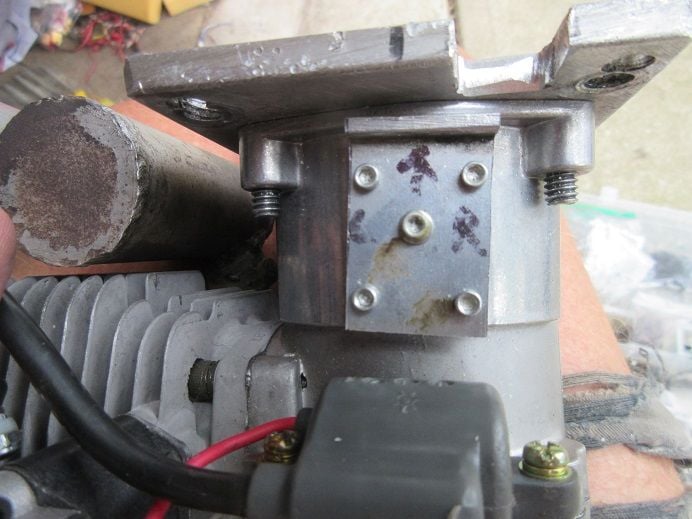
New engine mount plate.
Bought these about 10 years ago as 'spares'.
Spring starter added.
Metal back plate added.
Going to need all the weight possible with such a short 'nose' on this plane.
Need 8" for the prop to clear the cowl so lots of 'fire wall'.
Cut and screwed a 1/2" thick multi-ply to the original fire wall.
The 2nd piece of fire wall is a 'template' to insure the engine is off set enough to be in the center of the front of the cowl.
Will need a lot of 'washers' to have the correct 'off set'.
This metal plate will replace the 2nd wood template.
Here is the other electronic G-62 that I thought about using.
The inside of the cowl.
Guess the original owner was going to put a 3 cylinder engine in this plane.
I had to 'butcher it up' so the G-62 would 'fit'.
'Dry fit'.
Guess I should read this!
===================
Also, charged the batteries in the Z F6F Hellcat.
Last edited by samparfitt; 06-21-2024 at 04:54 PM.
 06-22-2024, 01:19 PM
#27
Black Horse Gilmore 84.5" racer ARF. (cont).
This morning I went to Carolyn park in Dayton, Ohio for their train fest.
This afternoon, I 'worked' on the Gilmore.
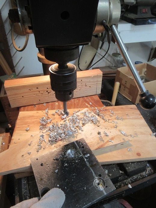
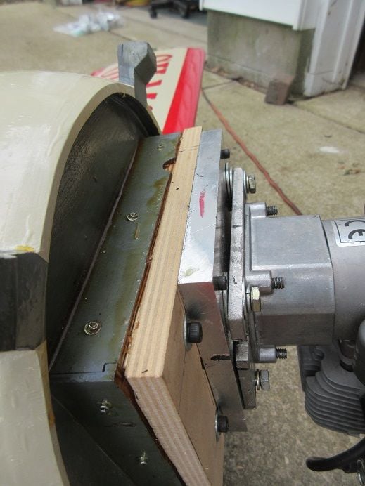
Needed to drill 2 recesses in the aluminum plate for the bolt heads that protrude on the 1/2" thick ply fire wall.
A carbide forstner bit 'worked'.
Used the aluminum plate to drill the 4 holes to secure the aluminum plate to the 1/2" thick ply firewall.
These 4 holes are for the engines mounting plate.
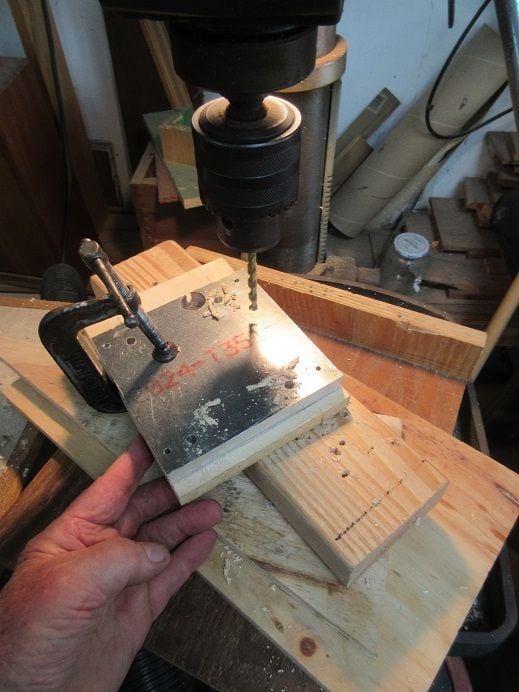
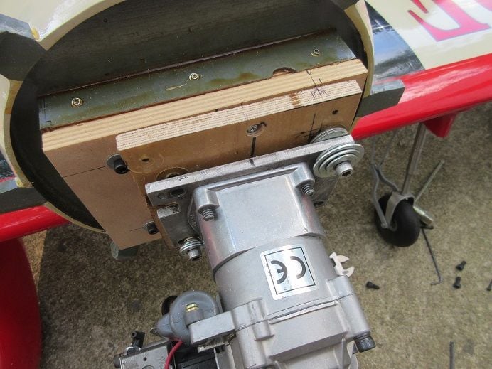
Had to move the bottom right bolt to the left so it wouldn't interfere with the engine mounting holes.
The aluminum plate is to the right of the 2 left black bolts so no recesses were needed for those bolts.
Four blind nuts (T nuts) were inserted on the back of the 1/2" thick ply fire wall.
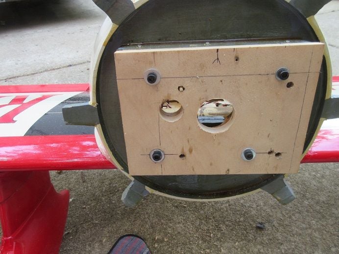
TA DA!
The 4 small black bolts hold the aluminum plate to the fire wall so it's easier to install the washers to the engine mounting plate without having the aluminum plate 'moving around'.
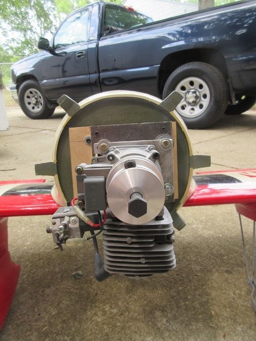
Washers added to give right and down thrust.
The metal plates insure no distortion of the engine which could cause internal wear.
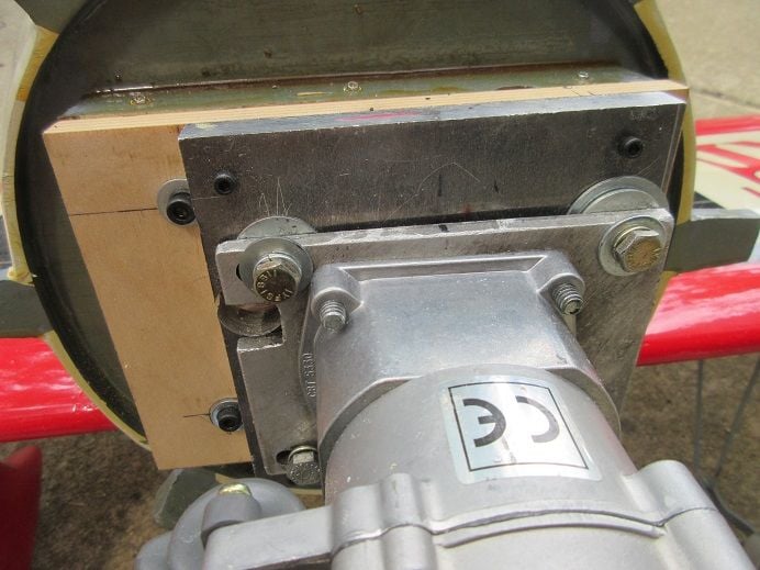
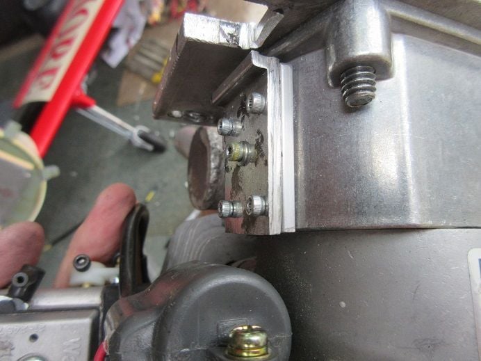
Two of the 4 small black bolts holding the aluminum plate to the fire wall.
Muffler.
Drilled out the metal behind where the nuts are located in those slots so the bolts can be tightened without having to add a bunch of washers to get the correct 'length'.
A very old muffler but functional.
Guess I could paint it with some heat resistant paint!
Has a tube so I can add 'smoke'.
Had to use the Dremel to remove some of the cowling for the exhaust.
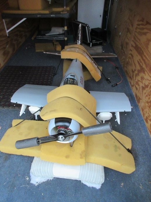
Prop will 'clear' the cowl.
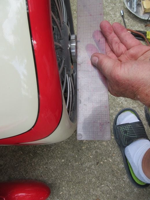
MMMM: those 'pants' are, probably, too low to the ground and will 'catch the grass'!
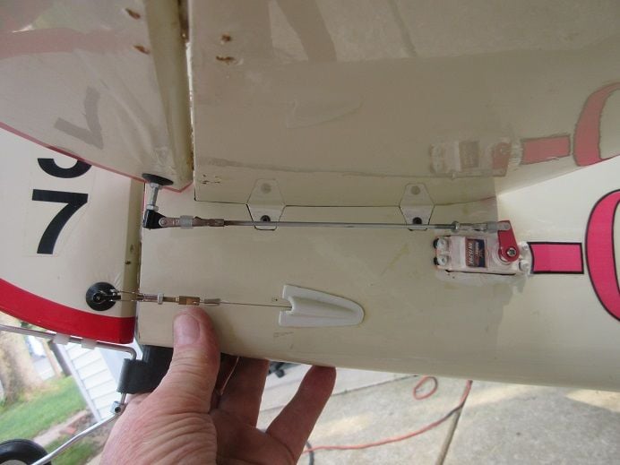
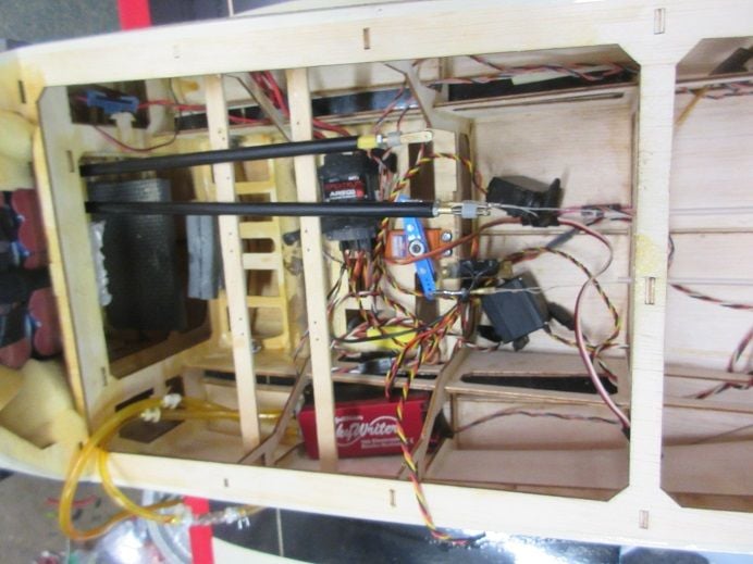
The manual has the elevator servos under the cockpit (the usual spot).
I favor 'short linkages' so I like what the previous owner did!
The CG is 3.54" from the LE and 'just using my fingers' for a 'guestimate' and it's close.
With 2 batteries, tank, throttle/choke servos, should be 'good'.
Next to install throttle/choke servos.
'poster' pictures!
This morning I went to Carolyn park in Dayton, Ohio for their train fest.
This afternoon, I 'worked' on the Gilmore.
Needed to drill 2 recesses in the aluminum plate for the bolt heads that protrude on the 1/2" thick ply fire wall.
A carbide forstner bit 'worked'.
Used the aluminum plate to drill the 4 holes to secure the aluminum plate to the 1/2" thick ply firewall.
These 4 holes are for the engines mounting plate.
Had to move the bottom right bolt to the left so it wouldn't interfere with the engine mounting holes.
The aluminum plate is to the right of the 2 left black bolts so no recesses were needed for those bolts.
Four blind nuts (T nuts) were inserted on the back of the 1/2" thick ply fire wall.
TA DA!
The 4 small black bolts hold the aluminum plate to the fire wall so it's easier to install the washers to the engine mounting plate without having the aluminum plate 'moving around'.
Washers added to give right and down thrust.
The metal plates insure no distortion of the engine which could cause internal wear.
Two of the 4 small black bolts holding the aluminum plate to the fire wall.
Muffler.
Drilled out the metal behind where the nuts are located in those slots so the bolts can be tightened without having to add a bunch of washers to get the correct 'length'.
A very old muffler but functional.
Guess I could paint it with some heat resistant paint!
Has a tube so I can add 'smoke'.
Had to use the Dremel to remove some of the cowling for the exhaust.
Prop will 'clear' the cowl.
MMMM: those 'pants' are, probably, too low to the ground and will 'catch the grass'!
The manual has the elevator servos under the cockpit (the usual spot).
I favor 'short linkages' so I like what the previous owner did!
The CG is 3.54" from the LE and 'just using my fingers' for a 'guestimate' and it's close.
With 2 batteries, tank, throttle/choke servos, should be 'good'.
Next to install throttle/choke servos.
'poster' pictures!
Last edited by samparfitt; 06-22-2024 at 01:26 PM.
06-23-2024, 11:32 AM
#28
Black Hawk Gilmore 84.5" racer assembly (cont).
Took around 6 hours just to install a B&B specialties 'double linkage' which converts horizontal movement to vertical movement,
which is needed for the G-62's throttle and choke.
Again, purchased this part about 10 years ago.
Holes for the 'push rods'.
Drilled/tapped 4/40 hole for the 'double linkage' screw in the side of the engine mounting plate.
Double linkage attached to the engine mounting plate.
A Dremel used to grind off the brass end shaft that holds the control horns that will be replaced with the 'double linkage' control horns.
Tapped 2/56 for the ball link to the Sullivan 'easy connects'.
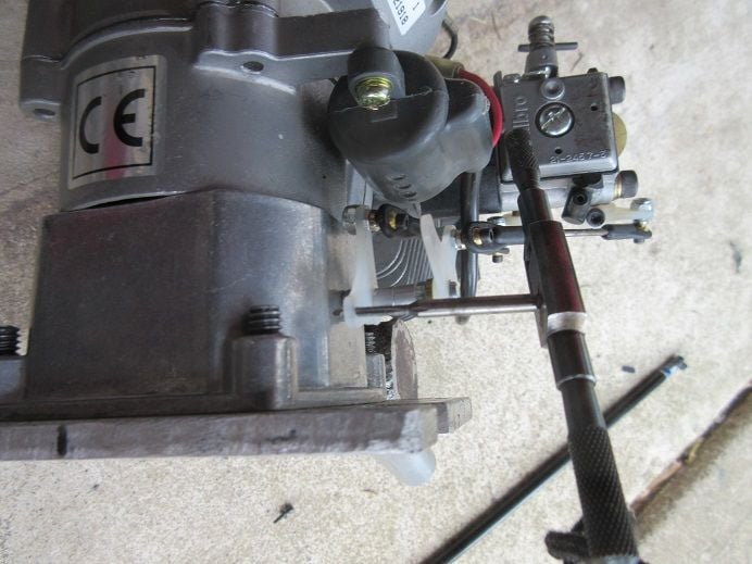
Ball links attached.
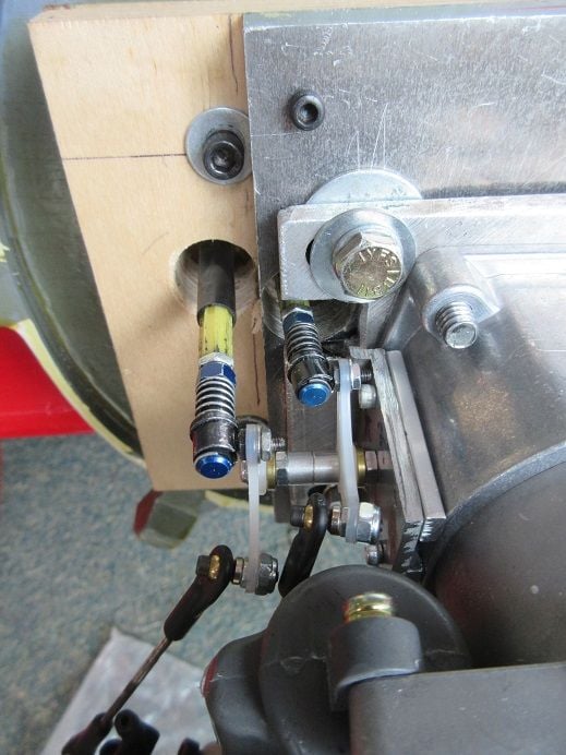
About a 3/32" of metal removed for control rod clearance.
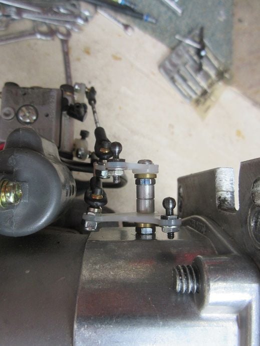
The control rods were not aligning with the 2 holes in the fire wall so I had to make a 1/4" thick metal plate to move the 'double linkage' to the left.
Used a damaged engine mounting plate for 'parts'.
Before using my power tools, I ask myself is this a 'safe move'; plyers to hold the part plus gloves.
A slow process.
Drill/tap center hole and align it with the existing hole in the engine mounting plate.
Drill all 4 'corner' holes, one at a time with screw in the last hole to insure next hole is accurate.
An 1/8"X1/4" piece along each side to raise the plate a 1/4".
Again each hole drilled/tapped, one at a time, screw inserted and do the next hole.
Insured no interference with 'spring starter' plus 'blow out' any metal particles.
Sullivan 'easy connects' attached and engine back on the fire wall.
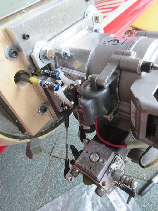
Had to remove one plate screw as it was interfering with the 'linkage'.
Next: install servos for throttle and choke and cut control rods to length.
============
Flying tomorrow.
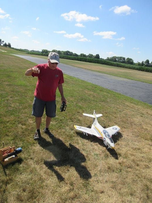
Got the Skyraider charged and maiden the new P-40.
Getting lazy: the Skyraider has remote engine starter.
Took around 6 hours just to install a B&B specialties 'double linkage' which converts horizontal movement to vertical movement,
which is needed for the G-62's throttle and choke.
Again, purchased this part about 10 years ago.
Holes for the 'push rods'.
Drilled/tapped 4/40 hole for the 'double linkage' screw in the side of the engine mounting plate.
Double linkage attached to the engine mounting plate.
A Dremel used to grind off the brass end shaft that holds the control horns that will be replaced with the 'double linkage' control horns.
Tapped 2/56 for the ball link to the Sullivan 'easy connects'.
Ball links attached.
About a 3/32" of metal removed for control rod clearance.
The control rods were not aligning with the 2 holes in the fire wall so I had to make a 1/4" thick metal plate to move the 'double linkage' to the left.
Used a damaged engine mounting plate for 'parts'.
Before using my power tools, I ask myself is this a 'safe move'; plyers to hold the part plus gloves.
A slow process.
Drill/tap center hole and align it with the existing hole in the engine mounting plate.
Drill all 4 'corner' holes, one at a time with screw in the last hole to insure next hole is accurate.
An 1/8"X1/4" piece along each side to raise the plate a 1/4".
Again each hole drilled/tapped, one at a time, screw inserted and do the next hole.
Insured no interference with 'spring starter' plus 'blow out' any metal particles.
Sullivan 'easy connects' attached and engine back on the fire wall.
Had to remove one plate screw as it was interfering with the 'linkage'.
Next: install servos for throttle and choke and cut control rods to length.
============
Flying tomorrow.
Got the Skyraider charged and maiden the new P-40.
Getting lazy: the Skyraider has remote engine starter.
06-24-2024, 11:10 AM
#29
Flying at the local field.
Excellent weather. low winds and cool in the morning on the 7:30 AM arrival.
Can't 'win'!
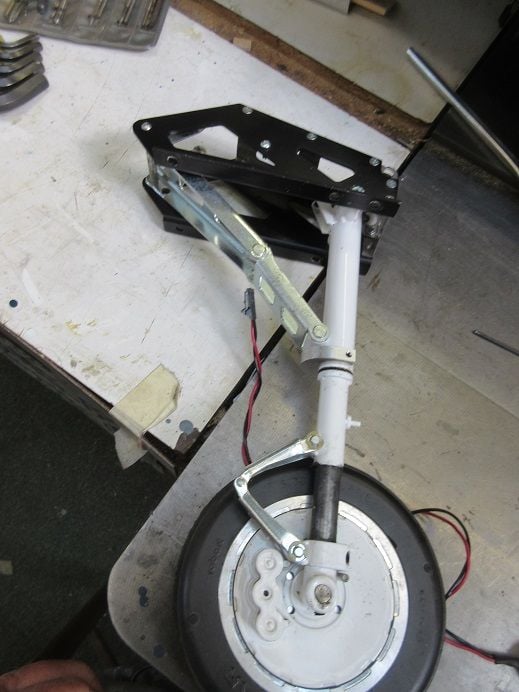
Gear on the Skyraider broke when testing them on the 'ground': My first electric retracts so I hope I can repair it.
Plane wouldn't 'bind': both batteries were 'low'.
Still June and over 8' high!

Excellent weather. low winds and cool in the morning on the 7:30 AM arrival.
Can't 'win'!
Gear on the Skyraider broke when testing them on the 'ground': My first electric retracts so I hope I can repair it.
Plane wouldn't 'bind': both batteries were 'low'.
Still June and over 8' high!
06-24-2024, 01:44 PM
#30
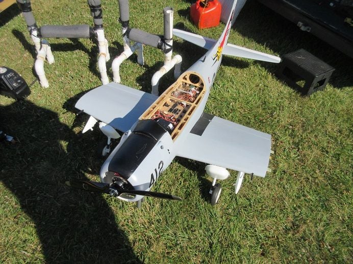
Legend hobbies A-1 Skyraider.
Robart actuator came apart while 'ground testing it'.
For the last 25 years I've used air retracts and this is my first set of electric retracts.
Any help on a repair would be appreciated.
I've sent an email to Robart inquiring about it.
thanks.
Robart actuator came apart while 'ground testing it'.
For the last 25 years I've used air retracts and this is my first set of electric retracts.
Any help on a repair would be appreciated.
I've sent an email to Robart inquiring about it.
thanks.
06-24-2024, 02:08 PM
#31
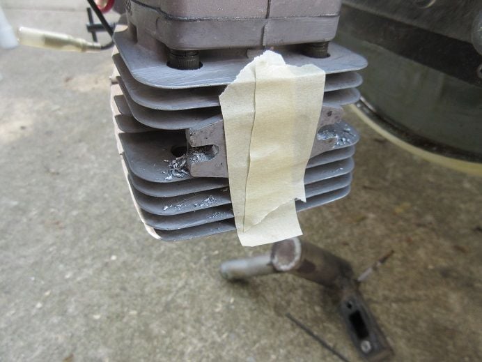
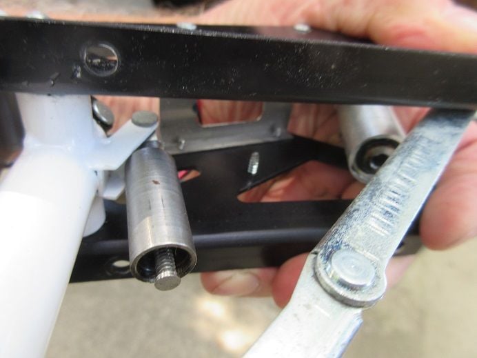
Did some research and found this disassembled actuator.
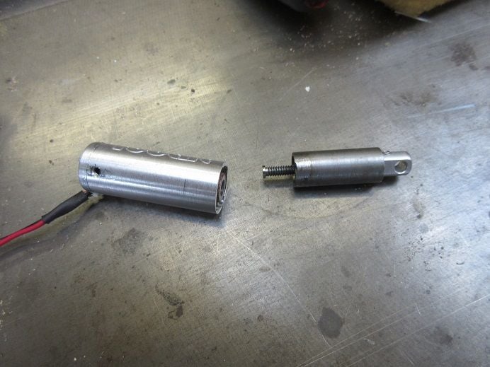
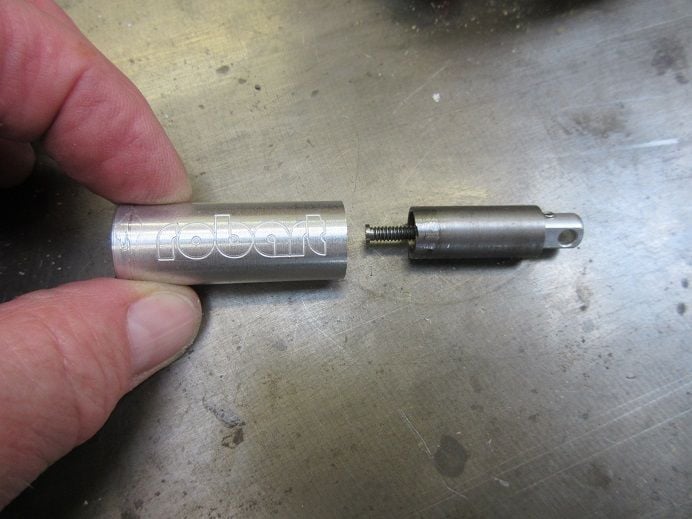
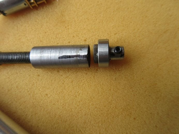
It appears that part of the large 'collar' broke off from the shaft (tube).
There is a set screw on the smaller part of the collar that connects the large tube to the motor shaft.
The large tube screws onto the inner threaded shaft which makes this assumption a logical deduction.
There is a 'burn mark' on my parts.
This 'burn mark' is only on one spot: that appears to be where the 'weld' was made.
In this case, it seems like there should have been at least 2 weld spots to secure the collar to the tube.
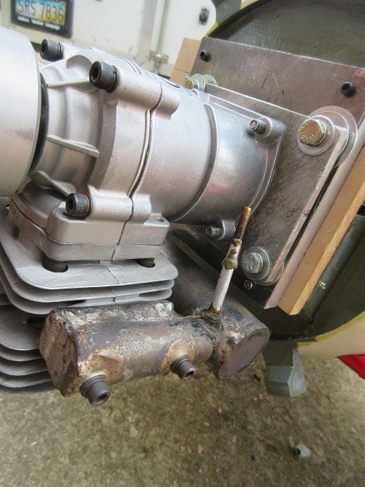
This also explains why I saw the actuator wobbling when I first obtained the plane; it was partial coming apart
and functioned until that weld broke.
The motor mechanism still works.
1) now I need to figure out how to disassemble the actuator
2) guessing Robart won't just sell me that one part but will have to buy a new actuator.
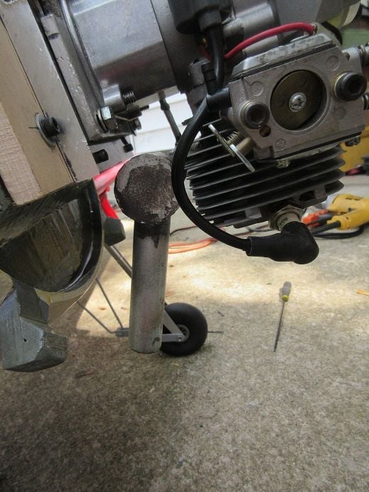
Inspecting the two broken parts it appears the collar slides into the tube about 3/32" in which case, if I can disassemble it,
it seems like some JB weld, applied sparingly, would secure the 2 parts!
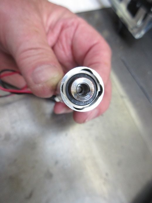
The end cap that has 2 wires coming out of it is either screwed on or 'force fit'.
If that cap could be removed it seems the entire mechanism will just 'slide out'.
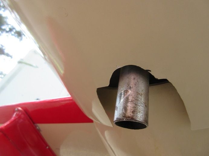
Before I start 'butchering up' the casing I will wait for Robarts response plus any on this thread.
Looking at the picture it appears the owner cut the outer casing in half as mine is one solid tube which seems like he destroyed that part.
I also found what appears to be a replacement motor that a pilot used in his retracts:
It appears that part of the large 'collar' broke off from the shaft (tube).
There is a set screw on the smaller part of the collar that connects the large tube to the motor shaft.
The large tube screws onto the inner threaded shaft which makes this assumption a logical deduction.
There is a 'burn mark' on my parts.
This 'burn mark' is only on one spot: that appears to be where the 'weld' was made.
In this case, it seems like there should have been at least 2 weld spots to secure the collar to the tube.
This also explains why I saw the actuator wobbling when I first obtained the plane; it was partial coming apart
and functioned until that weld broke.
The motor mechanism still works.
1) now I need to figure out how to disassemble the actuator
2) guessing Robart won't just sell me that one part but will have to buy a new actuator.
Inspecting the two broken parts it appears the collar slides into the tube about 3/32" in which case, if I can disassemble it,
it seems like some JB weld, applied sparingly, would secure the 2 parts!
The end cap that has 2 wires coming out of it is either screwed on or 'force fit'.
If that cap could be removed it seems the entire mechanism will just 'slide out'.
Before I start 'butchering up' the casing I will wait for Robarts response plus any on this thread.
Looking at the picture it appears the owner cut the outer casing in half as mine is one solid tube which seems like he destroyed that part.
I also found what appears to be a replacement motor that a pilot used in his retracts:
Last edited by samparfitt; 06-24-2024 at 02:34 PM.
06-25-2024, 02:39 PM
#32
Lengend hobbies A-1 Skyraider.
Mike at Robart said I need a new actuator and gave me the part number.
Will try to fix the old one for a 'back up'.
===============
Black Horse Gilmore 84.5" racer (cont).
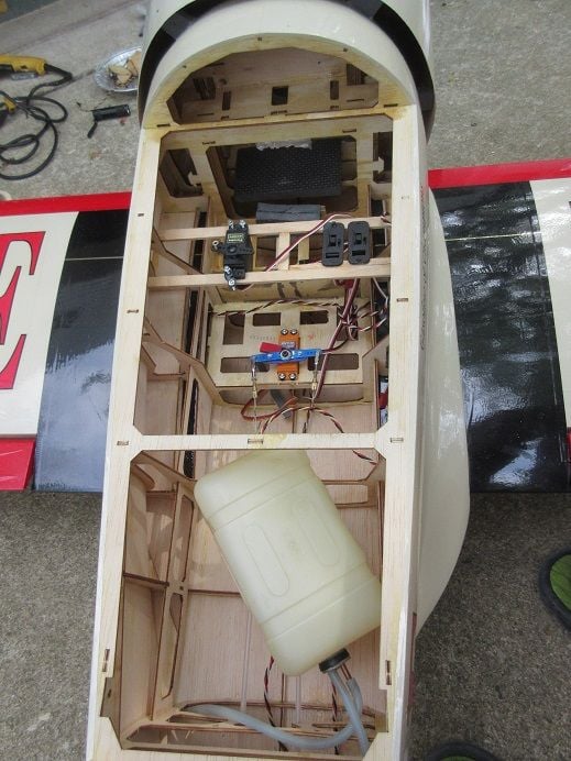
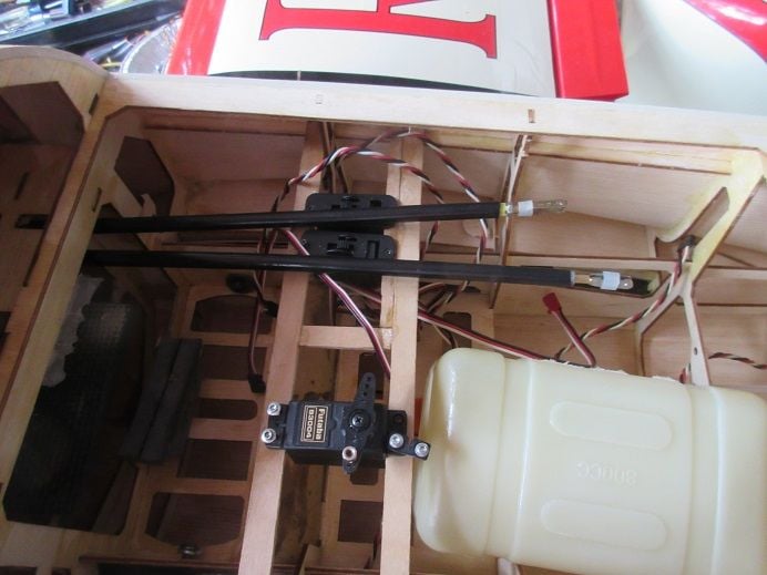
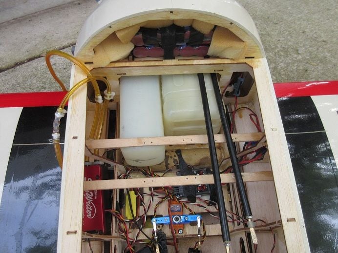
Receiver installation.
Put two 3,000ma 5 cell battery packs against the back fire wall which should help the CG.
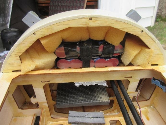
Receiver on the lower level tray.
Sullivan's smoke pump (red box) dry fitted.
The tank for the smoke is rotated 90 degrees to fit the 2nd former opening.
Binded the receiver to the transmitter.
Ailerons and elevator are only suppose to be 0.6 inches ( per manual) so 'adjustment' needed.
Rudder is suppose to be 0.8 inches.
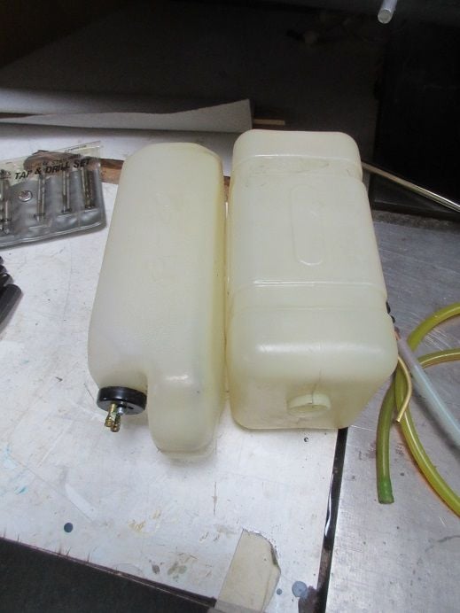
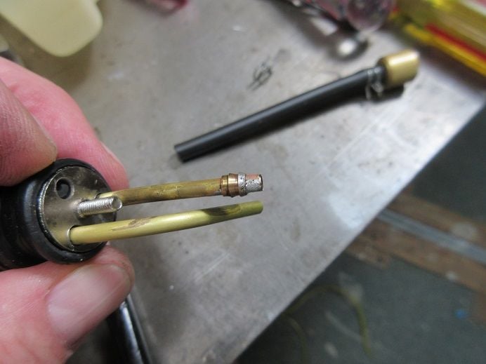
Was going to install the 'plumbing' but out of 'gas stoppers' and ordered 6 from Tower Hobbies.
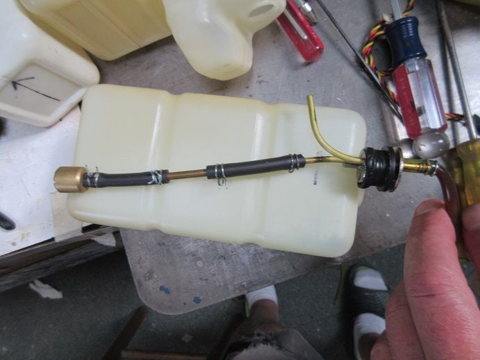
Soldered a 'barb' on the clunk tubing.
Dry fit.
CG is only 3.5" from LE so tanks are, virtually, over the CG.
Had to, temporarily, remove the throttle and choke servos to install the tanks.
Mike at Robart said I need a new actuator and gave me the part number.
Will try to fix the old one for a 'back up'.
===============
Black Horse Gilmore 84.5" racer (cont).
Receiver installation.
Put two 3,000ma 5 cell battery packs against the back fire wall which should help the CG.
Receiver on the lower level tray.
Sullivan's smoke pump (red box) dry fitted.
The tank for the smoke is rotated 90 degrees to fit the 2nd former opening.
Binded the receiver to the transmitter.
Ailerons and elevator are only suppose to be 0.6 inches ( per manual) so 'adjustment' needed.
Rudder is suppose to be 0.8 inches.
Was going to install the 'plumbing' but out of 'gas stoppers' and ordered 6 from Tower Hobbies.
Soldered a 'barb' on the clunk tubing.
Dry fit.
CG is only 3.5" from LE so tanks are, virtually, over the CG.
Had to, temporarily, remove the throttle and choke servos to install the tanks.
Last edited by samparfitt; 06-25-2024 at 02:49 PM.
Yesterday, 11:34 AM
#33
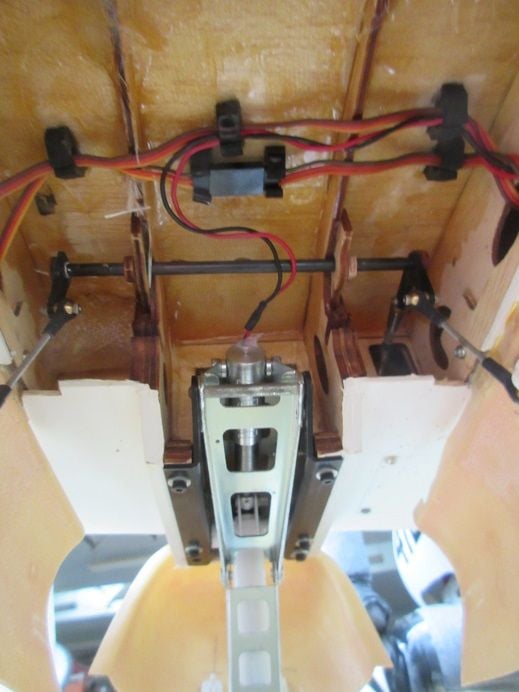
Legend hobbies A-1 Skyraider.
While 'waiting' for my new actuator to arrive from Robart thought I'd try repairing the 'broken one'.
Broken electric gear actuator.
1st method failed, went to method 2!
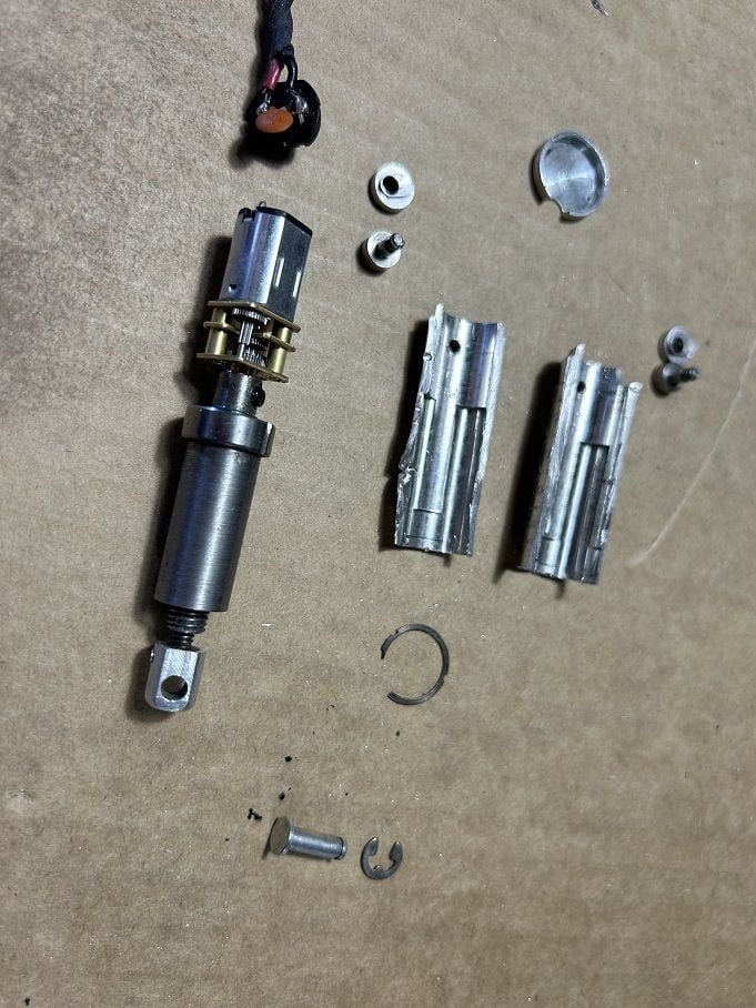
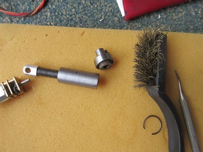
Actuator disassembly.
The end cap came off easily as it was just a 'force fit'.
I thought the inner mechanism would slide out the 'cap end' but I had to remove a 'C' ring on the other end.
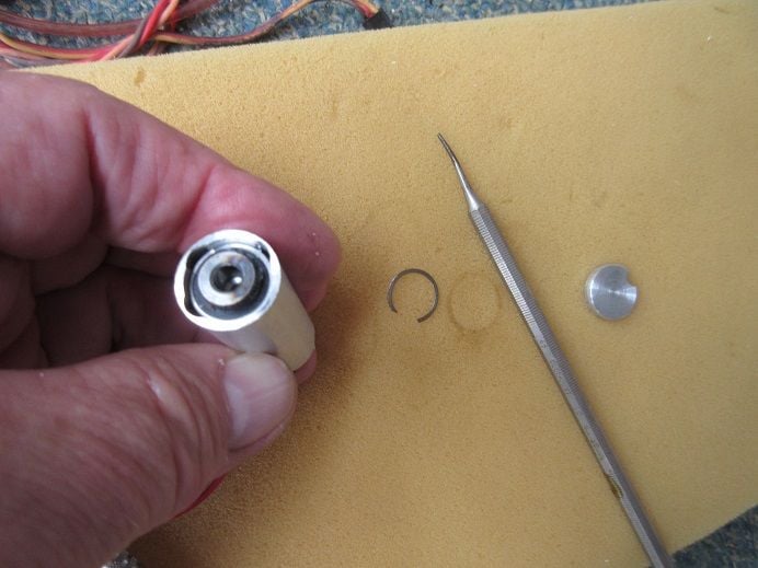
One of my 'scribing points' removed the 'C' ring.
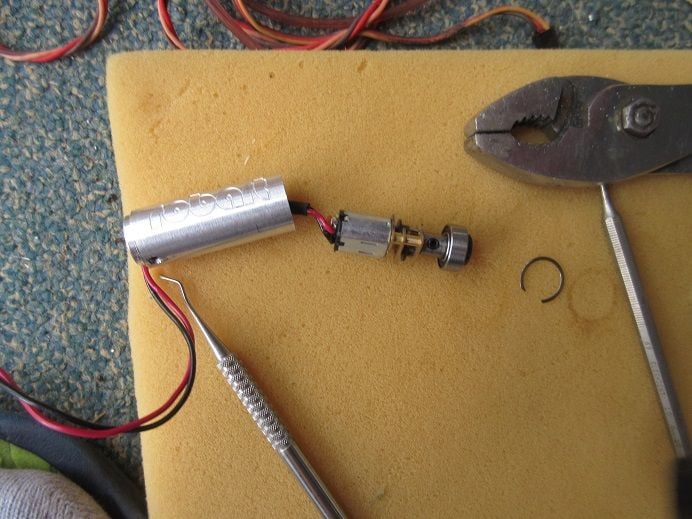
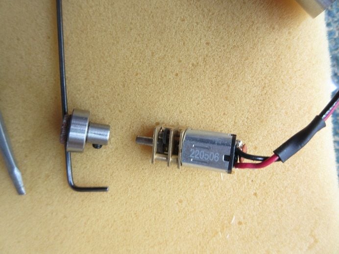
The motor was removed via a set screw so as to not damage it.
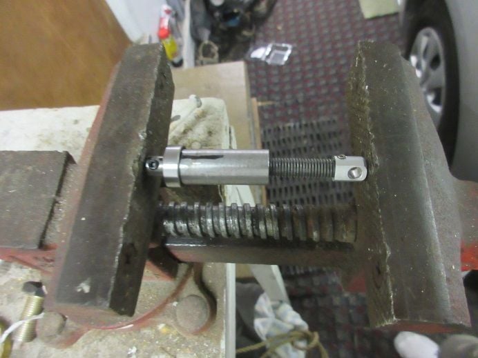
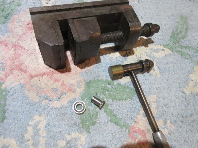
The two parts that 'mate' are grooved.
I figured I could clean up the mating surface and press fit them 'back together'.
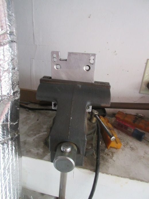
A vice used to press the two parts together.
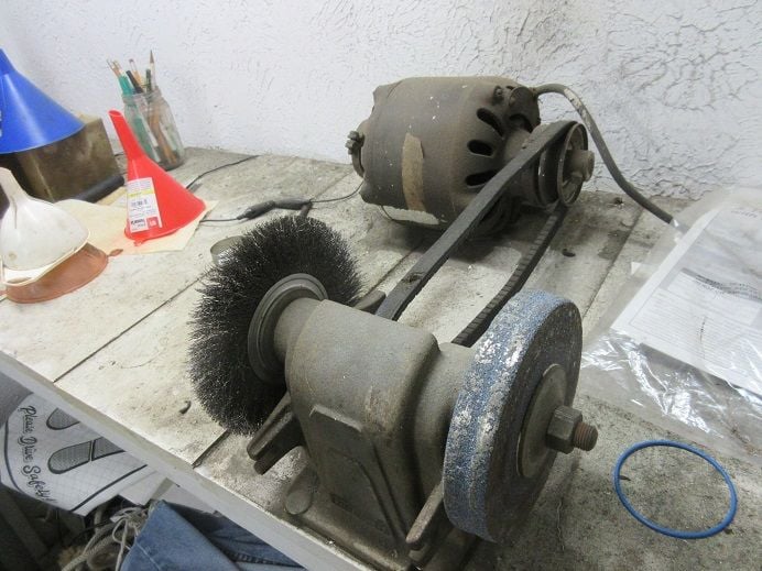
This was my dad's grinder back in the 50' using a washing machine motor for 'power'.
Stull functional after only 70 years
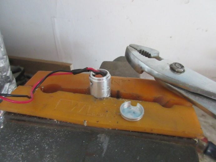
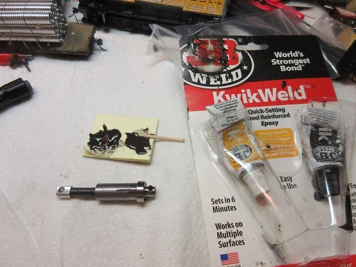
JB weld to secure the 2 parts.
Before 'complete' assembly, I tested it via the 'retract controller'.
Put the actuator on the gear but it failed in one direction; too much force is applied in one direction and separated the 2 parts.
Interesting in that there is only one tiny weld spot on the 2 parts where they meet.
This actuator was wobbling before it broke.
I'm guessing one side 'broke free' causing the wobble and, eventually, the welded side broke.
Will be interesting to see if the new actuator has 2 weld spots indicating that the old one was defective since it only had one weld spot!
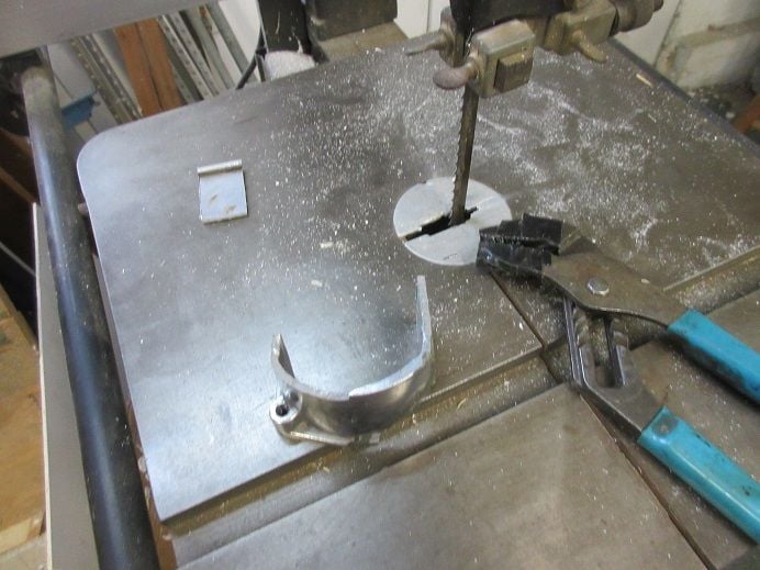
Method 2.
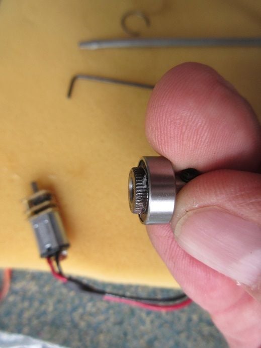
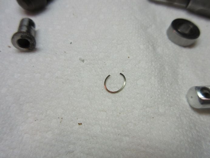
After another disassembly, the bearing needed to be removed to better connect the 2 parts.
I thought the bearing was a 'force fit' but there is a 'C' ring to secure it to the shaft.
Hopefully I didn't damage the 'C' ring!
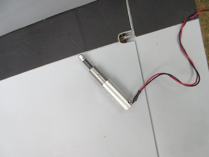
Glad I did this on the floor on a light blue carpet as the 'C' ring was easy to see!
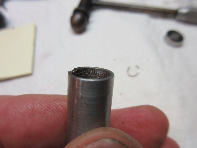
There is so much force applied that the ridges are 'ground down'.
I pressed fitted the 2 parts and took it to my auto mechanic and having him weld 2 spots (180 degrees apart) between the 2 parts.
I'll have to use the Dremel to grind down any excess.
See 'what happens'!
'Never say die; at least not yet'!
While 'waiting' for my new actuator to arrive from Robart thought I'd try repairing the 'broken one'.
Broken electric gear actuator.
1st method failed, went to method 2!
Actuator disassembly.
The end cap came off easily as it was just a 'force fit'.
I thought the inner mechanism would slide out the 'cap end' but I had to remove a 'C' ring on the other end.
One of my 'scribing points' removed the 'C' ring.
The motor was removed via a set screw so as to not damage it.
The two parts that 'mate' are grooved.
I figured I could clean up the mating surface and press fit them 'back together'.
A vice used to press the two parts together.
This was my dad's grinder back in the 50' using a washing machine motor for 'power'.
Stull functional after only 70 years
JB weld to secure the 2 parts.
Before 'complete' assembly, I tested it via the 'retract controller'.
Put the actuator on the gear but it failed in one direction; too much force is applied in one direction and separated the 2 parts.
Interesting in that there is only one tiny weld spot on the 2 parts where they meet.
This actuator was wobbling before it broke.
I'm guessing one side 'broke free' causing the wobble and, eventually, the welded side broke.
Will be interesting to see if the new actuator has 2 weld spots indicating that the old one was defective since it only had one weld spot!
Method 2.
After another disassembly, the bearing needed to be removed to better connect the 2 parts.
I thought the bearing was a 'force fit' but there is a 'C' ring to secure it to the shaft.
Hopefully I didn't damage the 'C' ring!
Glad I did this on the floor on a light blue carpet as the 'C' ring was easy to see!
There is so much force applied that the ridges are 'ground down'.
I pressed fitted the 2 parts and took it to my auto mechanic and having him weld 2 spots (180 degrees apart) between the 2 parts.
I'll have to use the Dremel to grind down any excess.
See 'what happens'!
'Never say die; at least not yet'!
Last edited by samparfitt; Yesterday at 11:43 AM.
