


HPI MT2 Electric conversion
 07-27-2024, 07:47 PM
#1

Thread Starter
Join Date: Jul 2007
Location: North West Indiana
Posts: 12,861
Likes: 0
Received 20 Likes
on
19 Posts
Well preface to this the Nitro HPI MT was my 1st RC I owned, and I have a soft spot for it. Over the years it got fully upgraded part by part to a Nitro MT2. I loved it so much I bought a box of MT parts off some guy, and in the box was 2 more MT1's in pieces 
Anyways 14-16 years back I tried converting one of the Nitro MT1's to electric, and it burned up a motor in about 2 minutes of running, it was slow, and the way I mounted the motor was extremely crappy.
But I still had the thought in my mind one day make a Nitro RS4 into electric.
Now after all that time I finally thought up of a way that will work, and get the right gearing, and that is using the Brama 10b(worst RC I've ever owned, or used I snapped its chassis going on stock power hitting the separation in concrete after 5 mins of its 1st use...) as the Brama 10b\E10's diffs are the same exact gearing as the RS4 MT's so no trying to find a particular big mod 1 spur gear to get it to the right gearing so it doesn't burn a motor up. Also the gearing ratio is very close to the Tamiya DF-02 which I know can handle what I'm going to throw at this
Anyways all that out of the way to the process.
1st I replaced the spur gear assembly with one off an HPI Brama 10b/E10. And to make sure I got the correct spacing for the drive shafts to drive the front and rear wheels I took the spur gear rod off the original MT1 spur gear, put it in a drill, and pushed it into the brama 10b spur gears center so it will fit on the shaft (the brama 10b's was slightly smaller). To center the gear on the shaft I put some teflon bushings that are used in place of bearings in lower end models to make the shaft hold the gear snug.
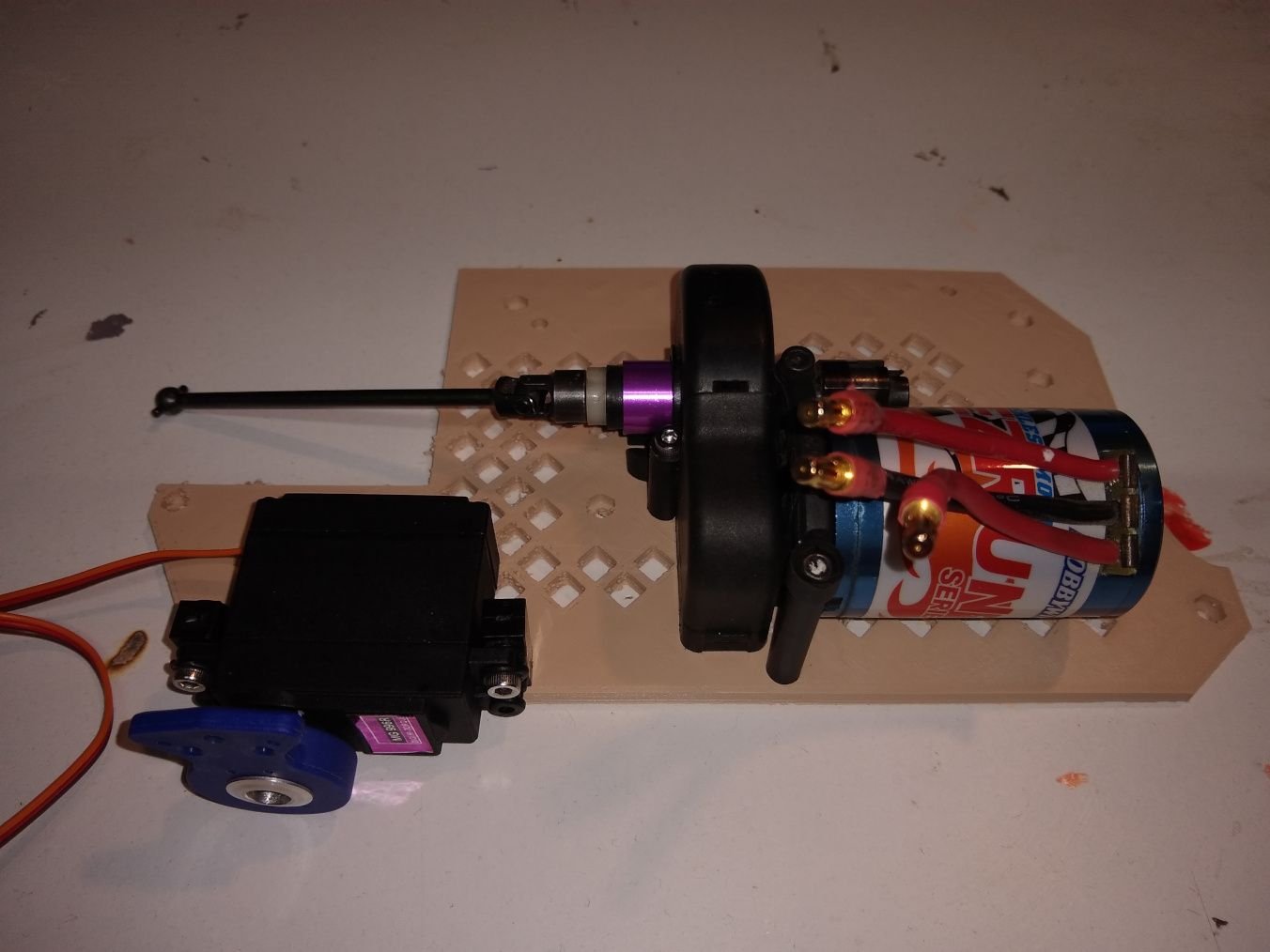
Next part is something I couldn't have done 14 years ago I designed a plate to screw the Brama 10b's gear box onto that then gets screwed down to the chassis plate of the MT2, and holds the center spur gear assembly, servo, and battery box
Here is a pic of the motor mount, and spur gear box, and servo before mounting it to the vehicle.
Now I will give the way I did the design with a short run through of the process I used, and software
I designed the spur gear section of the plate in like 20-30 mins in Tinkercad by taking measurements with my calipers, and plotting it out. I did a test print of just the spur gear section to make sure it could mount up. I took that test while the spur gear section was screwed to it, and used that to find a good spot on the chassis for it.
After that I then started to measure out the rest of the holes based on the test pieces location, and after measuring 2 holes as the holes were not on a plane that was being a pain to get the data off of I said screw it grabbed my phone, and took a few pictures of the plate with the piece I made taped to it in place.
I took the picture, and opened it in my graphics editor. I made transparent layer on top, and took the paint tool, and placed dots in the center of the holes on the chassis picture. I took that transparent layer, and loaded it into inkscape then had inkscape trace the holes, and exported the output to a svg which I loaded up in tinkercad into the field with the motor mount piece I made already.
Now if you ask why I did this it is easy I used the mount I made to scale the now model that I imported in of hole placements, and then I just made the plate using my knowledge... You know in my head its not hard, but after trying to write the process down in simplified way makes it seem insanely complicated.
Anyways 14-16 years back I tried converting one of the Nitro MT1's to electric, and it burned up a motor in about 2 minutes of running, it was slow, and the way I mounted the motor was extremely crappy.
But I still had the thought in my mind one day make a Nitro RS4 into electric.
Now after all that time I finally thought up of a way that will work, and get the right gearing, and that is using the Brama 10b(worst RC I've ever owned, or used I snapped its chassis going on stock power hitting the separation in concrete after 5 mins of its 1st use...) as the Brama 10b\E10's diffs are the same exact gearing as the RS4 MT's so no trying to find a particular big mod 1 spur gear to get it to the right gearing so it doesn't burn a motor up. Also the gearing ratio is very close to the Tamiya DF-02 which I know can handle what I'm going to throw at this
Anyways all that out of the way to the process.
1st I replaced the spur gear assembly with one off an HPI Brama 10b/E10. And to make sure I got the correct spacing for the drive shafts to drive the front and rear wheels I took the spur gear rod off the original MT1 spur gear, put it in a drill, and pushed it into the brama 10b spur gears center so it will fit on the shaft (the brama 10b's was slightly smaller). To center the gear on the shaft I put some teflon bushings that are used in place of bearings in lower end models to make the shaft hold the gear snug.
Next part is something I couldn't have done 14 years ago I designed a plate to screw the Brama 10b's gear box onto that then gets screwed down to the chassis plate of the MT2, and holds the center spur gear assembly, servo, and battery box
Here is a pic of the motor mount, and spur gear box, and servo before mounting it to the vehicle.
Now I will give the way I did the design with a short run through of the process I used, and software
I designed the spur gear section of the plate in like 20-30 mins in Tinkercad by taking measurements with my calipers, and plotting it out. I did a test print of just the spur gear section to make sure it could mount up. I took that test while the spur gear section was screwed to it, and used that to find a good spot on the chassis for it.
After that I then started to measure out the rest of the holes based on the test pieces location, and after measuring 2 holes as the holes were not on a plane that was being a pain to get the data off of I said screw it grabbed my phone, and took a few pictures of the plate with the piece I made taped to it in place.
I took the picture, and opened it in my graphics editor. I made transparent layer on top, and took the paint tool, and placed dots in the center of the holes on the chassis picture. I took that transparent layer, and loaded it into inkscape then had inkscape trace the holes, and exported the output to a svg which I loaded up in tinkercad into the field with the motor mount piece I made already.
Now if you ask why I did this it is easy I used the mount I made to scale the now model that I imported in of hole placements, and then I just made the plate using my knowledge... You know in my head its not hard, but after trying to write the process down in simplified way makes it seem insanely complicated.

The following users liked this post:
RustyUs (08-03-2024)
07-27-2024, 08:09 PM
#2
Thread Starter
Join Date: Jul 2007
Location: North West Indiana
Posts: 12,861
Likes: 0
Received 20 Likes
on
19 Posts
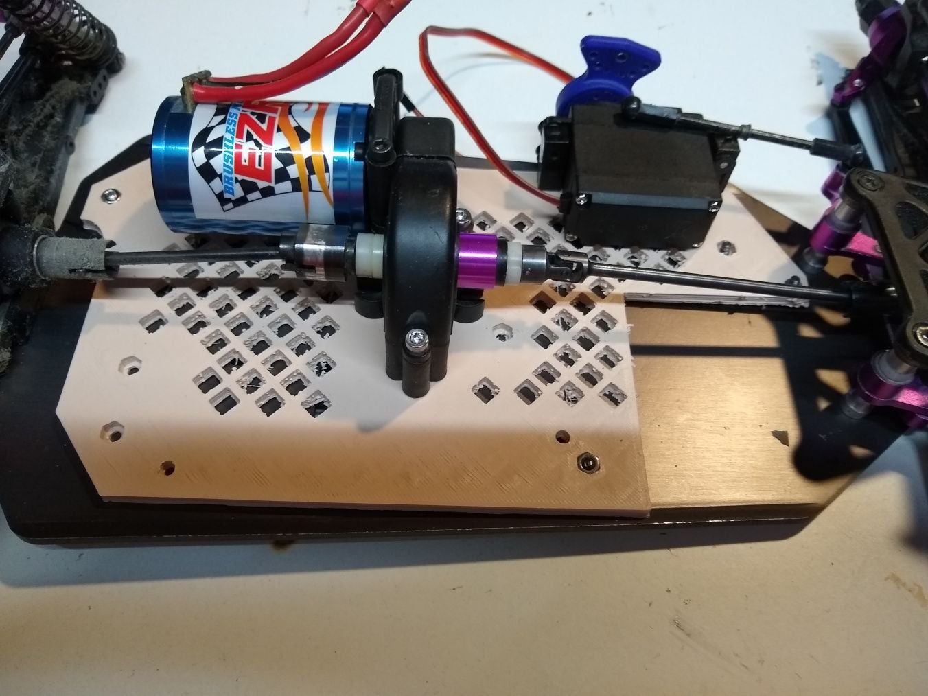
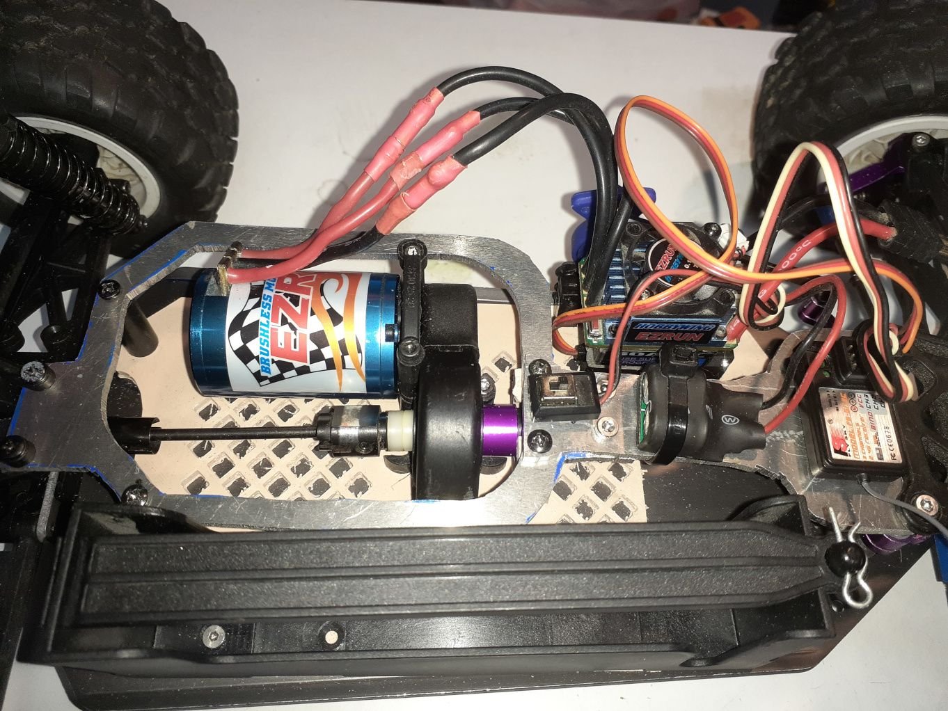
ANYWAYS (I'm breaking this up to make it easier) Here is an image of the plate screwed down to the chassis. I've yet to mount the battery holder which I'm going to use one from a Ofna NEXX SCRT10 that I happen to have spare from another project.
Unfortunately though not all the screw holes lined up correctly
For the holes that don't line up the majority are VERY close, and off maybe 1-3mm's. Thing I don't even think I need them as the plate is on very stable with what I got. Truthfully I was expecting more holes not to be 100% lined up due to the way I did the placement.that I outlined in that long section in the previous post. The part took 8 hours to print... You will also notice I flipped the servo over. The original placement was due to my original plan which was to use this in a HPI RS4 rally car I started making using the same chassis plate design(I smashed the stock bend in the front down on the RS4 rally plate to flatten it), but I decided right before I was going to screw motor plate to it to instead do the MT2.
The Rally rs4 is also missing a driveshaft that I can't find, and I'm not ordering any parts right now so yea I can always make another if I like it enough.
So this is where I am at now.
Edit as I didn't want to make another post:
Actually screwed the battery holder down.
It is terrifying how fast, and smoothly this build is coming together. I came up with the idea to try the bramas motor mount a day ago, and 4 hours later (took me 2 hours to find all the parts as they were in 3 different bins of random rc parts) I had the design for the mounting plate, and 13 hours later was mounting the stuff to it. I've spent $0 on this(outside the cost of the filament I used to print which was probably less then $1) as it was all scraps from old RC's I junked(the Brama), scrapped projects, or leftovers from upgrades.
If all goes well I might try to test it tomorrow as all it needs is the electronics tied down, and wheels put on it to run.
If all goes well I'm going to design some chassis braces to stiffen it up that will also cover the center driveshaft, and add places to mount the electronics.
I can use those holes that didn't line up properly to screw in the braces, and maybe cut some aluminum from damaged chassis's I got laying around to make it solid.
Last edited by SyCo_VeNoM; 07-27-2024 at 08:52 PM. Reason: added stuff to the bottom
07-28-2024, 03:58 PM
#3
Thread Starter
Join Date: Jul 2007
Location: North West Indiana
Posts: 12,861
Likes: 0
Received 20 Likes
on
19 Posts
whoo boy this thing rips took it out for a 5 minute test as its hot, and humid out.
After 5 mins the motor was getting pretty hot as I could only touch it for like 2-3 seconds before I had to pull away. Unfortunately over the 10-14 years since I was really into RC I have no idea where my IR Thermometer disappeared to.
hmm I might end up putting this setup into the RS4 rally car I have as the tires are quite a bit smaller, and should alleviate some of the burden on the motor. 1st I think I'll get a IR thermometer though
The following users liked this post:
RustyUs (08-03-2024)
08-03-2024, 12:21 PM
#4
Thread Starter
Join Date: Jul 2007
Location: North West Indiana
Posts: 12,861
Likes: 0
Received 20 Likes
on
19 Posts
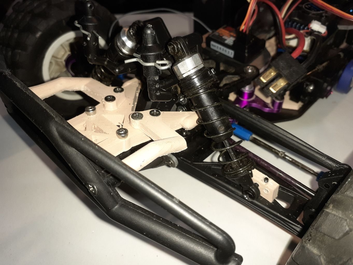
Well I changed some stuff one it is no longer a MT2 as I put those parts back on the Nitro chassis I had sitting. I instead made it a more closer to a MT1 though out of scrap parts I had from some I had. I say more like as it has parts from a few different RS4's mix and matched.
The front shocks, rear shocks, rear shock tower, front shock mounts(I had to 3d print some as I could only find one), all body mounts, rear arms, differentials, uprights, and tires are from a RS4 MT1 same with body
The front A-arms, c-hubs, knuckles, and chassis plate are from a RS4 MT2(I would have used MT1, but couldn't find a MT1 c-hub >.>)
The front shock tower, and front arm mounting hub are from a RS4 Rally
I custom made a bumper mount that is based on the RS4 rallys body mount piece that was also a brace.
Bumper is from an axial SCX10 that I had spare from my kit.
Battery box is from a Nexx10 SCRT
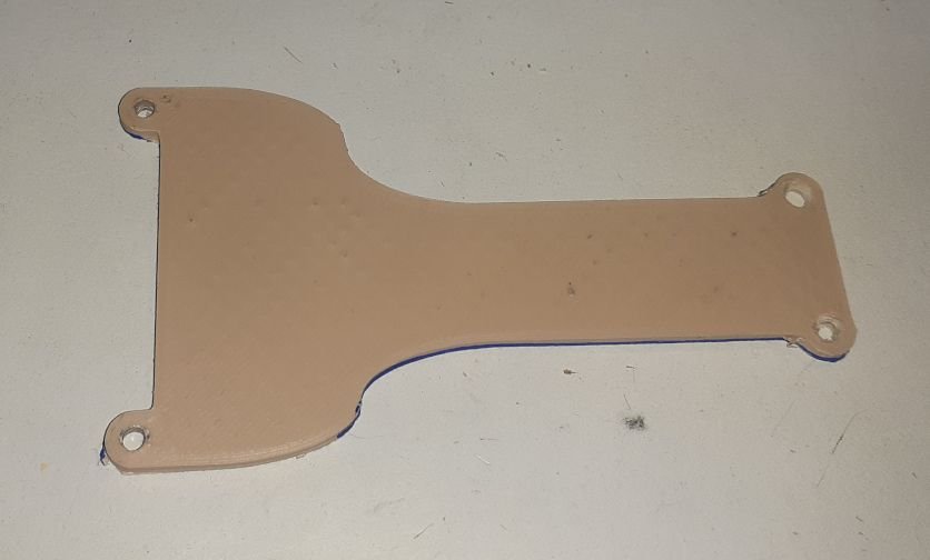
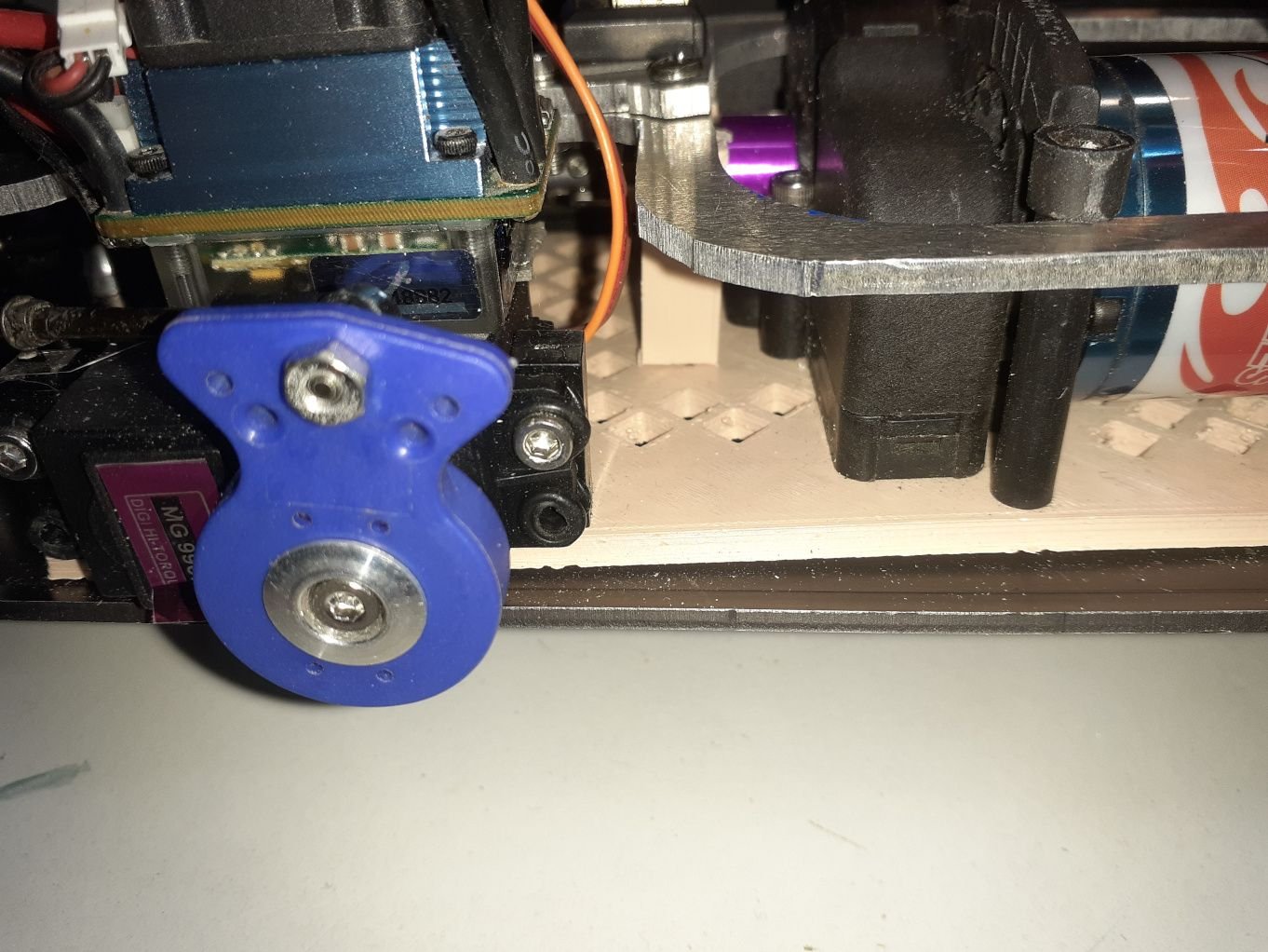
Well here are pics of chassis braces I made as there was some flex in the chassis, and I also needed a place to mount the electronics.
Here is the 1st iteration I made. It is 3mm thick
It screwed into a piece I made that is mounted to the chassis, and encircles the driveshaft.(I don't have a clear pic of it so no picture).
But anyways there was still too much flex as it did really nothing as the mount piece was just moving with the flex so I designed a piece that went from the front mount to the rear differential.
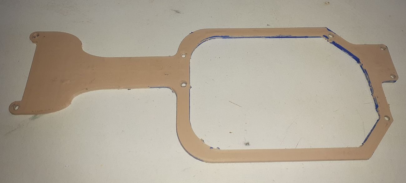
This went perfectly between the spur mount, and the battery box, and around the motor. I also had to make some posts that screwed into the chassis. I 3d printed 2, but they split in half when I put a screw in so I instead grabbed a delrin rod I had left from when I was modding RC's often, and just cut 2 piece of that to the exact size of the 3d printed mounts that split.
It eliminated a tiny bit of flex, but it was flexing itself in the center spot where it does the ring.
The front shocks, rear shocks, rear shock tower, front shock mounts(I had to 3d print some as I could only find one), all body mounts, rear arms, differentials, uprights, and tires are from a RS4 MT1 same with body
The front A-arms, c-hubs, knuckles, and chassis plate are from a RS4 MT2(I would have used MT1, but couldn't find a MT1 c-hub >.>)
The front shock tower, and front arm mounting hub are from a RS4 Rally
I custom made a bumper mount that is based on the RS4 rallys body mount piece that was also a brace.
Bumper is from an axial SCX10 that I had spare from my kit.
Battery box is from a Nexx10 SCRT
Well here are pics of chassis braces I made as there was some flex in the chassis, and I also needed a place to mount the electronics.
Here is the 1st iteration I made. It is 3mm thick
It screwed into a piece I made that is mounted to the chassis, and encircles the driveshaft.(I don't have a clear pic of it so no picture).
But anyways there was still too much flex as it did really nothing as the mount piece was just moving with the flex so I designed a piece that went from the front mount to the rear differential.
This went perfectly between the spur mount, and the battery box, and around the motor. I also had to make some posts that screwed into the chassis. I 3d printed 2, but they split in half when I put a screw in so I instead grabbed a delrin rod I had left from when I was modding RC's often, and just cut 2 piece of that to the exact size of the 3d printed mounts that split.
It eliminated a tiny bit of flex, but it was flexing itself in the center spot where it does the ring.
Last edited by SyCo_VeNoM; 08-03-2024 at 12:31 PM.
08-03-2024, 12:43 PM
#5
Thread Starter
Join Date: Jul 2007
Location: North West Indiana
Posts: 12,861
Likes: 0
Received 20 Likes
on
19 Posts
As for why there is blue on it I will explain that I took those pictures after this next step as I work faster, and get so in the zone on things I forget to do things.
Anyways I took those pieces, and then traced them to a piece of 3mm aluminum I had from the 1st time I tried to make a electric MT1 chassis. I forgot the grade as its been like 10 years since I bought it, but I can say it takes way more force to make a minor bend in it then ANY aluminum RC chassis plate I've had. So this thing is NOT going to flex at all.
So anyways I took the 2 parts I 3d-printed, and traced the pieces out on it using a blue paint marker(why there are blue marks in the above pics). I decided to make it easier to cut so I split the big piece down the center so my bandsaw could cut out the middle easier, and I drilled 2 extra holes in each piece to attach em so its solid.
Then as I originally designed it for a single 3mm plate I had to modify the center mount point as nothing was lining up right.
Again I skipped pics as I forgot, but here is it installed with the electronics mounted
Here is the best picture I could get of the center mount piece I made wish I remembered to take a picture when I had it out as I had to cut it down by 3mm's due to stacking the 2 plates I made
The following users liked this post:
kistner (08-04-2024)
08-03-2024, 12:50 PM
#6
Thread Starter
Join Date: Jul 2007
Location: North West Indiana
Posts: 12,861
Likes: 0
Received 20 Likes
on
19 Posts
Also here is the bumper mount I made
That was based on the RS4 Rally braces
I designed it in 3 pieces so it was easier to 3d print, is a little stronger, and was easier to install then if I made it one piece.
So that is basically it as I feel it is done I will do one last update with pics when I run it the weather has not been very nice these past few days.
I did forget to make a spot to hold the antenna which I will make today. I'll post a picture of that when I post the final pics of it after its 1st run completed.
I will say one thing though it will be a nightmare to change the spur, or pinion. I might have to drill a hole through the chassis plate so I could run the screw that holds the pinion mount so its easier to access.
I also might reprint the parts in black when I get around to ordering a spool as the PLA I used was kinda old, and leftover from a real big project I started, and kinda stalled on also I don't really like how the parts look on it with that beige(what I used the majority for was beige though), also that is why there are so many imperfections in the printed parts you can see.
Seriously wish I had the 3d printers I got now way back when I was really into RC I would have saved SO much money that I spent on random parts trees in hopes they would work, and prototyping parts. This went so fast, and smooth it isn't funny compared to the nightmare that I had prior for mediocre results.
Next project will prolly be modifying a 1/24th scale or so redcat I have laying around
Last edited by SyCo_VeNoM; 08-03-2024 at 12:57 PM.
08-08-2024, 08:56 PM
#7
Thread Starter
Join Date: Jul 2007
Location: North West Indiana
Posts: 12,861
Likes: 0
Received 20 Likes
on
19 Posts
OKAY new update the screw that held the motor in that set the mesh for the pinion came loose so I'm scrapping most of what I did as I had to remove 24-28 screws to get to that one along with everything outside the front, and read differential it took me over 30 minutes to get to that one screw....
The RC was also overheating the motor, but that I think might have been partially caused by when I installed the ziptie for the capacitor bank I put it around the driveshaft too when I tightened it.
Anyways what I'm going to use from the build is the front aluminum chassis plate, battery box, the MT1 parts for the spur(the dogbone/cvd, and the spur holder), and that it. I'm leaving the front bumper I don't count that in this.
Basically I took the MT2 spur gear, and cut all the teeth off just leaving the spokes. I then took that with the shaft you put the spur on, and mounted it in my drill press to use it as a improved lathe, and took a piece of sandpaper to make sure it was as close to balanced as possible by removing the same amount of material from each spoke.
I then took a 80 something tooth(I lost my place at like 75, and its not marked) spur, and drilled out the center making sure to let the bit line it up to center to make the hole a little bigger. I also let it spin freely on the drill to make sure it was as close to center as I could get.
Then I placed it on the MT spurs spokes, and drilled holes into it so I could screw it down.
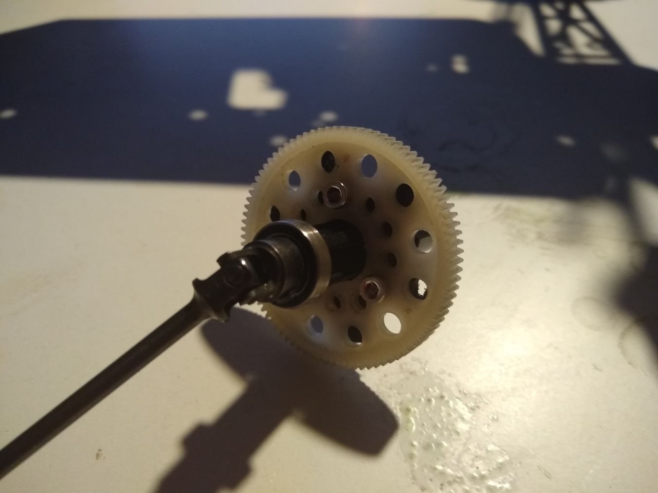
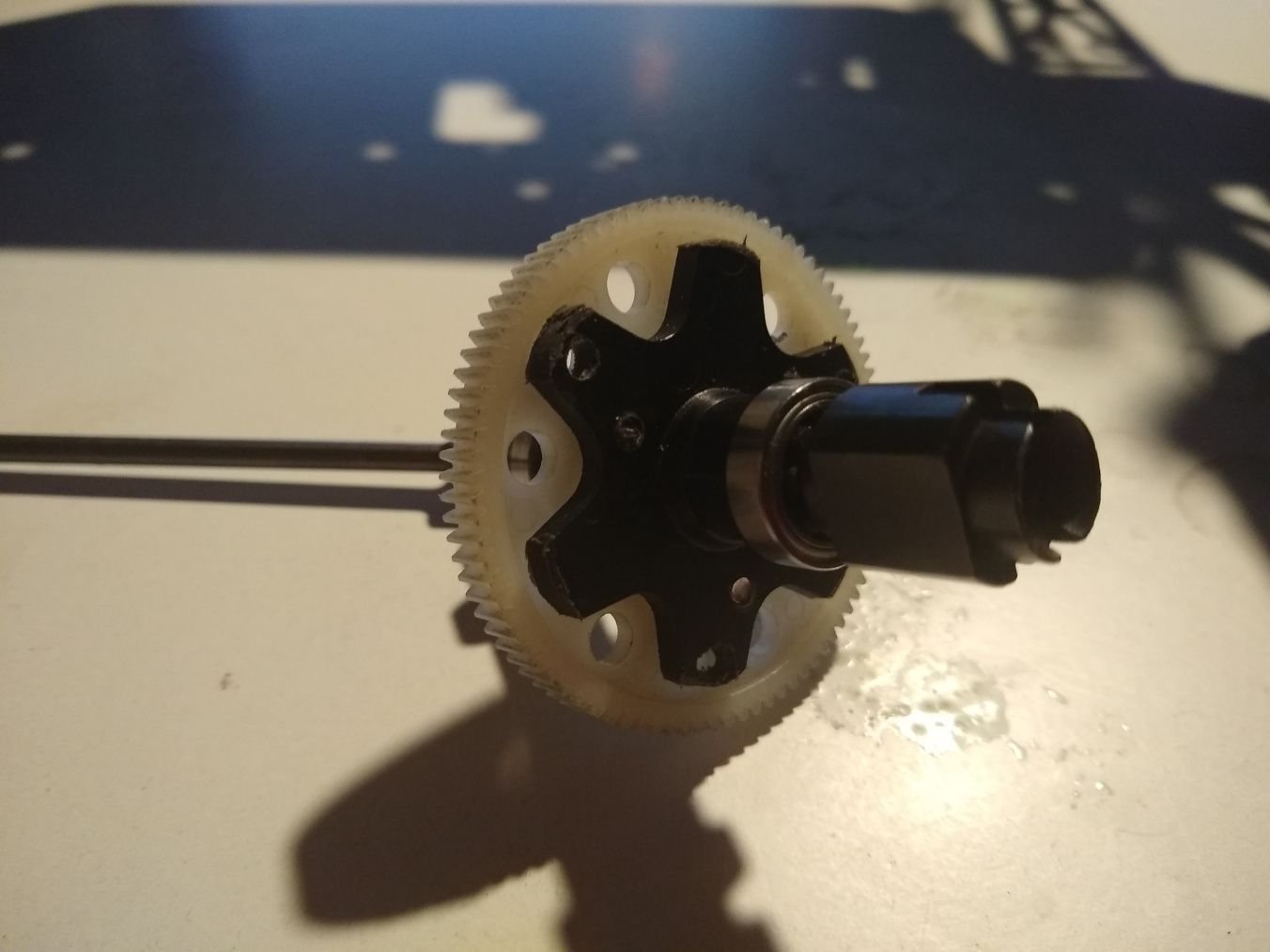
like so
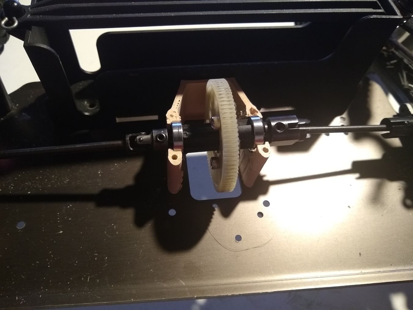
seeing that my wild idea worked I then went and started designing a new holder for it as I need the opening to be on the opposite side.
So I decided to make a test piece to check the alignment, make sure it cleared the battery box, and give me a visual idea of what I should do to mount the motor as the final version will have the motor mount built in.
Here is a pic showing the new progress.
This complete revisions goal is to make is so I can do whatever gearing I feel like, to be able to change the pitch to what suits the purpose best, and so I don't have to rely on e10 gears as it can now accept pretty much any spur.gear.
Spur I used I think was from my 2wd stampede, or was a spare I don't know actually.
Goal for tomorrow draw out the servo plate in cad, print it up, and get the servo installed. Might also try to have a prototype of the motor mount made.
The RC was also overheating the motor, but that I think might have been partially caused by when I installed the ziptie for the capacitor bank I put it around the driveshaft too when I tightened it.
Anyways what I'm going to use from the build is the front aluminum chassis plate, battery box, the MT1 parts for the spur(the dogbone/cvd, and the spur holder), and that it. I'm leaving the front bumper I don't count that in this.
Basically I took the MT2 spur gear, and cut all the teeth off just leaving the spokes. I then took that with the shaft you put the spur on, and mounted it in my drill press to use it as a improved lathe, and took a piece of sandpaper to make sure it was as close to balanced as possible by removing the same amount of material from each spoke.
I then took a 80 something tooth(I lost my place at like 75, and its not marked) spur, and drilled out the center making sure to let the bit line it up to center to make the hole a little bigger. I also let it spin freely on the drill to make sure it was as close to center as I could get.
Then I placed it on the MT spurs spokes, and drilled holes into it so I could screw it down.
like so
seeing that my wild idea worked I then went and started designing a new holder for it as I need the opening to be on the opposite side.
So I decided to make a test piece to check the alignment, make sure it cleared the battery box, and give me a visual idea of what I should do to mount the motor as the final version will have the motor mount built in.
Here is a pic showing the new progress.
This complete revisions goal is to make is so I can do whatever gearing I feel like, to be able to change the pitch to what suits the purpose best, and so I don't have to rely on e10 gears as it can now accept pretty much any spur.gear.
Spur I used I think was from my 2wd stampede, or was a spare I don't know actually.
Goal for tomorrow draw out the servo plate in cad, print it up, and get the servo installed. Might also try to have a prototype of the motor mount made.
The following users liked this post:
suburban_hooligan (08-10-2024)
08-13-2024, 03:38 PM
#8
Thread Starter
Join Date: Jul 2007
Location: North West Indiana
Posts: 12,861
Likes: 0
Received 20 Likes
on
19 Posts
well I took a few days off working on this as my 3d printers are tied up making a body for my army truck which I decided to work on as I hit a wall in my thought process on how it should be designed(mainly on the spur/pinion cover) which cleared up today.
I decided to make the spur, and pinion to be completely enclosed, and finished the design. To cover the hole that is under the spur I designed a 2mm plate that screws under the chassis into holes used that hold the center gear mount on.
It will be 8 screws to change the spur, 1 to change the pinion, and 2 to move the motor for meshing it to gears, or to remove it
08-20-2024, 11:50 AM
#9
Thread Starter
Join Date: Jul 2007
Location: North West Indiana
Posts: 12,861
Likes: 0
Received 20 Likes
on
19 Posts
Okay I finished the design, made it, and tested it
here is the final results
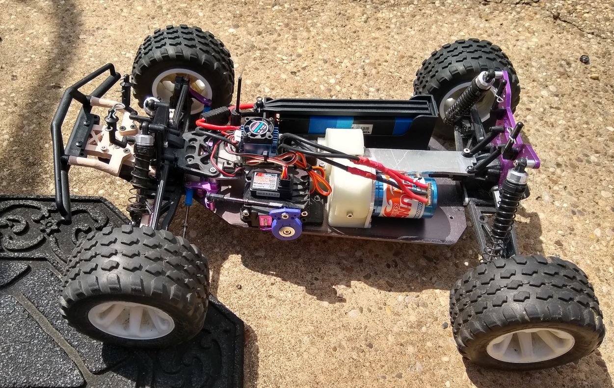
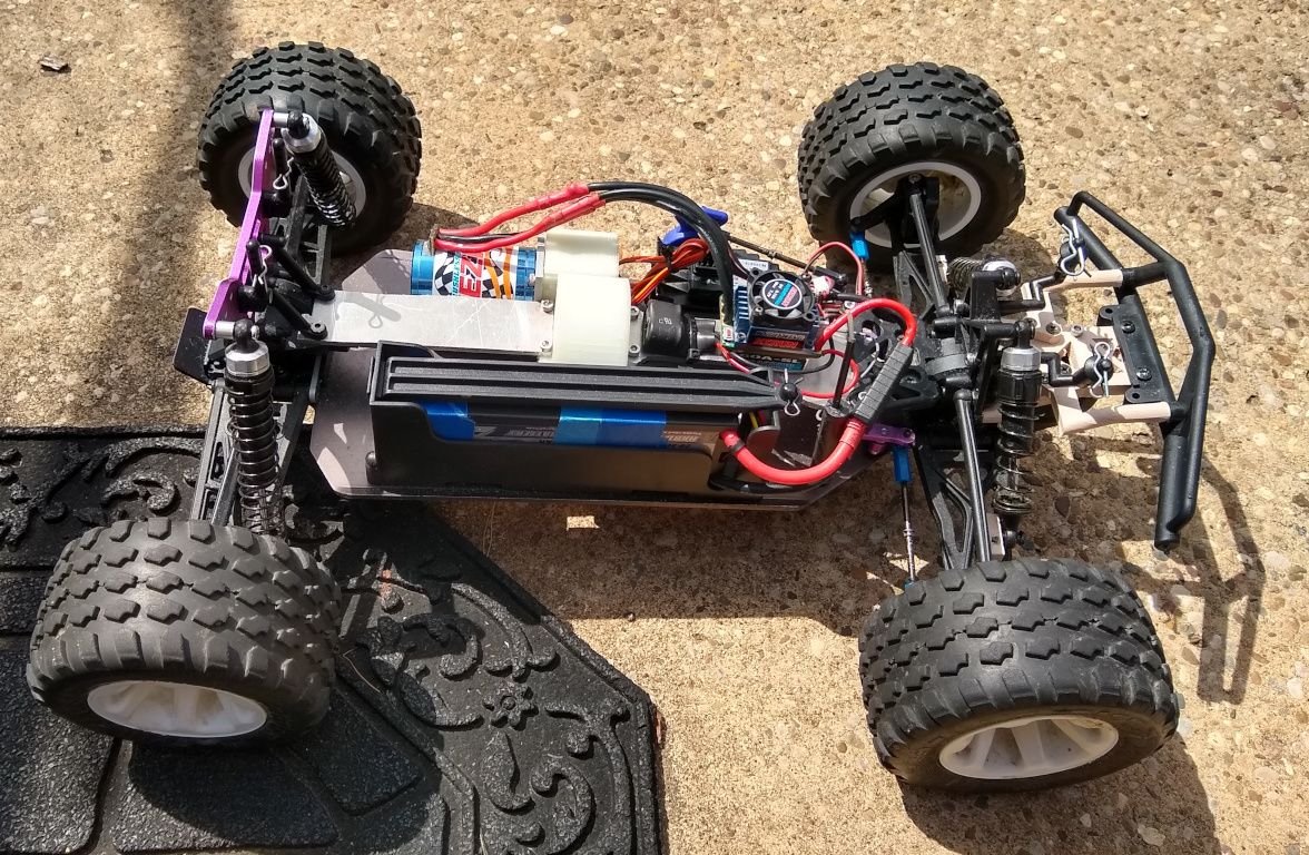
The test was good with the tires as it I did around 15 mins of full throttle driving(mostly through tallish grass), an the motor hit 135 degrees after all that time.
Now I moved the ESC, its capacitor bank, and switch to the center brace for 2 reasons. One is I wasn't comfortable with how I had to have it sit partially off the servo due to the steering linkage when it was at full throw would hit it. The other is if I want to dismantle it I had to either take the servo off, and the center brace, or replace the tape. This was I can just take the 4 screws off, unplug it from the radio, and the motor wires, and its off.
The pinion can be changed with 1 screw, the spur needs 8 to be taken off(the front and rear braces have to come off)
From the previous edition that used a E10/brama 10b gearbox the amount of screws has been reduced DRASTICALLY as prior it was something like 28 screws to change the pinion spacing now it is 1 to come out, and 2 to adjust it. Hell it is now 13 to completely remove everything from it(17 if you count the servo, and battery box). 5 hold the gearbox onto the chassis, 1 holds the pinion gear cover, 8 hold the spur(most those also double up as other things like 2 are part of the steering).
But yes this thing can take up to a 85 or 90t spur with a 22t pinion(might be larger as it does have a tiny bit of room to spare, but that is largest I could test)
This also should be able to fit on a onroad RS4 nitro chassis(not the original as that was belt drive) as it uses literally the stock screw holes that held on the center spur gear holder. although it would need different braces as the RS4 onroad was a bit shorter
Plans I'm going to redesign the spur/pinion gear cover, and I will print it out of PETG soon as currently it is in glow in the dark PLA which has a kinda low deformation temp, and honestly at 135 it was about 5 degrees from the temperature PLA starts to deform, and melt. Reason I used the PLA was I got it cheap(it was on sale), and I knew I would need to do it multiple times as this one was the 3rd print of it as I had a few measurements off on the 1st iteration(like 2-3mm's), and the 2nd I went to assemble and the motor mount screw was too close to the motor so I moved that to get the current version. The motor mount is made of aluminum I cut out fast, but screws into the PLA
here is the final results
The test was good with the tires as it I did around 15 mins of full throttle driving(mostly through tallish grass), an the motor hit 135 degrees after all that time.
Now I moved the ESC, its capacitor bank, and switch to the center brace for 2 reasons. One is I wasn't comfortable with how I had to have it sit partially off the servo due to the steering linkage when it was at full throw would hit it. The other is if I want to dismantle it I had to either take the servo off, and the center brace, or replace the tape. This was I can just take the 4 screws off, unplug it from the radio, and the motor wires, and its off.
The pinion can be changed with 1 screw, the spur needs 8 to be taken off(the front and rear braces have to come off)
From the previous edition that used a E10/brama 10b gearbox the amount of screws has been reduced DRASTICALLY as prior it was something like 28 screws to change the pinion spacing now it is 1 to come out, and 2 to adjust it. Hell it is now 13 to completely remove everything from it(17 if you count the servo, and battery box). 5 hold the gearbox onto the chassis, 1 holds the pinion gear cover, 8 hold the spur(most those also double up as other things like 2 are part of the steering).
But yes this thing can take up to a 85 or 90t spur with a 22t pinion(might be larger as it does have a tiny bit of room to spare, but that is largest I could test)
This also should be able to fit on a onroad RS4 nitro chassis(not the original as that was belt drive) as it uses literally the stock screw holes that held on the center spur gear holder. although it would need different braces as the RS4 onroad was a bit shorter
Plans I'm going to redesign the spur/pinion gear cover, and I will print it out of PETG soon as currently it is in glow in the dark PLA which has a kinda low deformation temp, and honestly at 135 it was about 5 degrees from the temperature PLA starts to deform, and melt. Reason I used the PLA was I got it cheap(it was on sale), and I knew I would need to do it multiple times as this one was the 3rd print of it as I had a few measurements off on the 1st iteration(like 2-3mm's), and the 2nd I went to assemble and the motor mount screw was too close to the motor so I moved that to get the current version. The motor mount is made of aluminum I cut out fast, but screws into the PLA
08-21-2024, 03:49 PM
#10
Thread Starter
Join Date: Jul 2007
Location: North West Indiana
Posts: 12,861
Likes: 0
Received 20 Likes
on
19 Posts
just noticed a real bad issue that I got to resolve. I can't change the pinion to a smaller one due to the center brace is hitting the motor mount. I'm going to have to cut around 4-5 mm's into the center rear brace to give the motor the ability to fully move in.
Otherwise I'm doing a minor design change to the full mount. By minor I'm just adjusting the thickness of the wall next to the pinion as the nut pops out that holds the cover on, and getting rid of some of the fillets that made printing harder, and less stable. Also making it so the pinion, and spur cover meet in a better spot so I had to do more adjustments like making the motor mount section 3mm's wider which also adds in more support for the nut that holds the motor to it, and again this too will make the printing easier for the parts.
Mechanically it won't have any change as none of the holes, or part sizes are changing that interact with the gears
