


What have you done to your RC today?
 08-08-2024, 08:13 PM
#576

Join Date: Jul 2007
Location: North West Indiana
Posts: 12,861
Likes: 0
Received 20 Likes
on
19 Posts
cool
I just took apart my electric MT1... or I should say I did what is necessary to adjust the pinion's spacing... it took me taking out 26 screws, 2 chassis braces, 3 spacers(2 of which needed pliers shoved in), removing the battery box, removing all the electronics, and removing 2 driveshafts JUST to get to the pinion adjustment screw that came loose. This is another of the main reason's I'm redoing it outside gearing lol
Next version to change the spur gear will be 8 screws to remove mainly due to the braces (it if wasn't for them it would be 4) which will be straight forward to install/remove, and 2 screws to take the motor out, or adjust the pinion spacing, and the electronics will stay in place as they were. out of that massive base plate that the stuff mounted to.all I'm keeping is the spacing for the servo.
I got black PLA+ in this week so it will look way nicer then the old stuff I was using when I print the final part after testing. Still going to use the old stuff for testing purposes though. or I could make it glow in the dark as I also got a spool of glow in the dark
Also think I found out why it was getting the motor so hot I did something stupid that I only noticed when I did a complete tear down. When I put a ziptie on the brace to hold the capacitor bank for the ESC down I accidentally put it around the driveshaft, and the zip tie was putting force on that. I'm shocked the ziptie didn't melt from the friction. Just another reason why the super complicated way I did it was kinda not good. Makes me feel like an automotive engineer designing modern cars that are overly complicated for no reason, and impossible to work on without taking out a stupid amount of things..
Last edited by SyCo_VeNoM; 08-08-2024 at 08:17 PM.
 08-09-2024, 03:41 PM
#577
Join Date: Jul 2007
Location: North West Indiana
Posts: 12,861
Likes: 0
Received 20 Likes
on
19 Posts
took the pede out today with HPI blitz tires on it. After 15-20 mins of driving it where at least 70% of the time was full throttle the motor hit the grand temperature of 124 degrees. Then again it was around 70(maybe a little lower) out just now, and the sun was mostly set. So I'll probably put back on the other tires as it was most likely the ambient heat, and sun that contributed to the motor getting near the borderline of burning up
08-09-2024, 04:20 PM
#578

i would have though a zip tie around a driveshaft would cause noticeable driveline friction 
which reminds me i need to take a look at why the driveline in one of my Dromida's is to tight.
which reminds me i need to take a look at why the driveline in one of my Dromida's is to tight.
08-10-2024, 01:53 PM
#579
Join Date: Jul 2007
Location: North West Indiana
Posts: 12,861
Likes: 0
Received 20 Likes
on
19 Posts
hmm I thought it would cause enough friction to melt the zip tie to be honest there was barely a mark on it. Well I also didn't zip tie it down to max force as I didn't need to I just needed it to hold it to the double sided tape which was keeping it from slipping so honestly I'm not sure if it did or didn't play a part in the motors temps..
Well too a break today from working on the redo of the MT1 to work on a different project which I kinda forgot about for 6 years which is my 6wd deuce, and a half which is made from axial, and wheely king parts(I started on it like 10 years ago) I finally got around to designing the bed of it now to print it. Had to break it up into 4 parts, and those parts are estimated by the 3d slicer that they are going to take a total of around 80 hours
I'll try to get it done in 2 days running 2 of my printers non-stop
Mechanically the thing runs great, and its pretty bullet proof the only thing is I just never finished the body.
I'll probably continue the design though of the motor mount for the E-MT1 as I ran into a slight issue I worked around, but it kinda makes the mount not look that good, and makes it a little convoluted to make, but I'm still going for least amount of screws as possible to make adjustments, or take stuff off.
Last edited by SyCo_VeNoM; 08-10-2024 at 01:59 PM.
08-10-2024, 02:53 PM
#580
80 hours to print 4 parts. is that all 4 at the same time or printing one at a time? you run that continuously or can you shut it off for a few hours and pick up where it left off? id be leery of leaving something like that running over night while i was asleep.
08-10-2024, 10:37 PM
#581
Join Date: Jul 2007
Location: North West Indiana
Posts: 12,861
Likes: 0
Received 20 Likes
on
19 Posts
parts are one at a time like the 1st part has been going 7 hours, and says it has 18 left(the estimations are generally way off)
I was planning to run 2 of my 3 printers, but the 2nd one is down. Few months back the software that controls it storage died, and I had to reinstall the software, and it has been acting up since. I spent 5-6 hours messing with it to try and get it to work, and I FINALLY found out why(they changed something from automatic to manually having to be done, and I had no idea I also damaged its $16 print surface that I JUST replaced...), but it will take a few more hours of tinkering to get it working right.
As for your idea about turning it off and continuing later. There are 2 sets of firmware ppl generally use for 3d printers. The one named Marlin DOES have that feature, but it doesn't always work that good. I on the other hand use what is called klipper which runs a bit different, and has a lot of customization, and modding for it( as well as a web interface that I can upload stuff remotely to the printer), and to my knowledge turning it off, and continuing isn't supported.
3rd printer is kinda down as I need a new print surface for it I had a glass one, but it kinda cracked after 3 or so years of use. I wasn't too happy with it anyways so meh. But yea I only use that one for smaller things as it has a somewhat slightly smaller print bed, and is kinda loud. It was also my 1st printer, and has been modded to the point that I think 80% of it was changed.
As for how safe it is... honestly if the firmwares safety settings are set right it is pretty safe. Unlike when my 1st printer was stock, and on stock firmware the company that made it had every safety setting disabled, and the printer almost started on fire as it was doing thermal runaway(it DID melt a bunch of wires) due to them stupidly using a crappy connector on the print bed. The firmware I run now is set to kill power if anything goes up by a few degrees, or if a sensor stops sending data.
For example I've heard people run 1-200 printers 24/7 making parts, and never heard of them having a fire.
Last edited by SyCo_VeNoM; 08-10-2024 at 10:42 PM.
08-11-2024, 01:34 PM
#582
Join Date: Jul 2007
Location: North West Indiana
Posts: 12,861
Likes: 0
Received 20 Likes
on
19 Posts
so the 1st part finished printing, and... I made a mistake in a measurement making it unusable(front tire mus guard thing slams into the tire), but also holding it near the truck itself kinda makes it look odd like I based it on a 3d model of a deuce and a half I found lifting all the measurements, but when held upto the cab in reality it just looks weird.something it didn't look in the cad software.
Think I'm going to drastically change how it is made, and make it more modular so I can say add a canvas top, or swap to an open design with railing like I see so many pics of the real thing have. On the plus side it should DRASTICALLY cut down on the print time as there is less initially to print, and I'm also scaling it so the pieces will be thinner, and when I do print the rails I can print them easier then it would be with it in one piece
Edit: Ok fixing that took way longer then I expected. In all honesty didn't change the scale of the parts much I did make them more uniform, and fixed their spacing, and made it even more modular to print.
Now the bed will take around 50 hours total to print this is over 20 hours less then the prior one. Before it was broken into quarters not it is only split in half. Also I'm glad I redid quite a bit as the tailgate wouldn't have worked as I had the hinge geometry wrong, now that is fixed. Also made the mudflaps to 4 more parts that have to be screwed on that alone cut down on 6 hours as it no longer needs to support them while printing sure it adds 8 screws but meh. Now to start printing this thing lol.
Last edited by SyCo_VeNoM; 08-11-2024 at 07:07 PM. Reason: didn't feel like a new post for some trivial update.
08-12-2024, 04:44 PM
#583
Join Date: Jul 2007
Location: North West Indiana
Posts: 12,861
Likes: 0
Received 20 Likes
on
19 Posts
today tried cleaning up the cab by sanding the imperfections and filler down for my deuce and a half scaler that I made 6 years ago as I started, and never finished... honestly I it is way too rough, and not worth fixing I say that after spending 15 mins with a belt sander trying to get the parts smooth.. the original one was printed in 9 pieces, and held together by a crapton of jb weld which I also used as a sudo bondo to smooth some of the extremely rough layer lines, and to try and make the parts fit together. I think I'm going to reprint it from scratch, and assembled the parts in cad, and cut it up differently then the original designer did so it is 2 big parts(and 5 smaller parts the original 9 didn't count the small parts too) now instead of how it was originally cut up into 12 parts(I merged 6 prior to printing it initially years ago).
The 1st half of the bed has 7 hours left(according to estimates) as I type, I already printed the mudflaps, and tailgate on my other printer, and am printing the rails.
As for the scale aspect it is like 15% wider one to fit the tires
The 1st half of the bed has 7 hours left(according to estimates) as I type, I already printed the mudflaps, and tailgate on my other printer, and am printing the rails.
As for the scale aspect it is like 15% wider one to fit the tires
08-17-2024, 11:39 AM
#584
Join Date: Jul 2007
Location: North West Indiana
Posts: 12,861
Likes: 0
Received 20 Likes
on
19 Posts
Well here is what I was working on since.
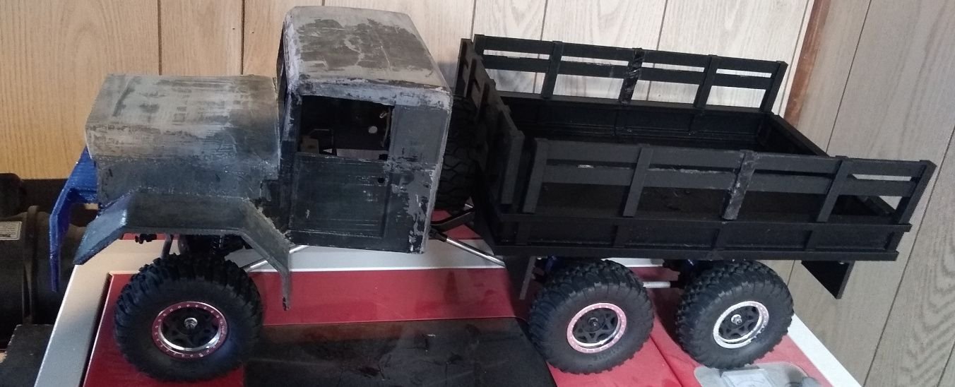
The bed is pretty much completely made it needs finishing work like sanding, and filling in spots where I joined the parts as I had to melt them together. I used a propane soldering iron on a low heat to join em. I tried glue, but it just wouldn't work due to not being able to have anything in the middle of the bed to join it due to it being too thin unlike how I have 2 dowels in the I beam sections per side.
You can also see how bad the cab looks in comparison
Still got to remake the cab so mad I wasted a lot of plastic on the back of the cab as it ran out when it was 97% done, and I didn't notice it was low >.>
But yea the remake of the cab will fix that low slanted rear stance.
Thinking about moving the battery to the cargo bed, and making some cargo boxes to cover it. Would be way easier then taking the cab on and off to put in a battery, and plus it would make the adding of lights to it easier as I wouldn't have to worry about the cab coming on and off. I happened to have bought a led kit many years ago which I never used (had plans to use it in a jeep I was trying to make) that adds brake lights turn signals, and headlights to an RC, and some of the choices I did in the design were made with this possibility in mind.
Last edited by SyCo_VeNoM; 08-17-2024 at 11:42 AM.
The following users liked this post:
suburban_hooligan (08-17-2024)
08-17-2024, 04:01 PM
#586
Join Date: Jul 2007
Location: North West Indiana
Posts: 12,861
Likes: 0
Received 20 Likes
on
19 Posts
cab, and bed is like 15% wider then it would be if it was 100% scale. Would have needed some larger diameter tires, but at the same width to get it truly scale(which I might not have needed that tire behind the cab)
height wise it is very close with all of the images, and things I could find for the back.
One reason it looks off is the back of the cab is sitting way too low in the back as I had made the hole for the gearbox too high as it was done before the front bumper was made(it actually doesn't look bad without the front bumper). If I would hold it up so the bottom of the door's line aligns with the bed it looks right. The redo the rear of the cab will sit like 30mm's higher, and be in line.
08-17-2024, 07:09 PM
#588
Join Date: Jul 2007
Location: North West Indiana
Posts: 12,861
Likes: 0
Received 20 Likes
on
19 Posts
yea in person it looks more like this but if the bed was straight
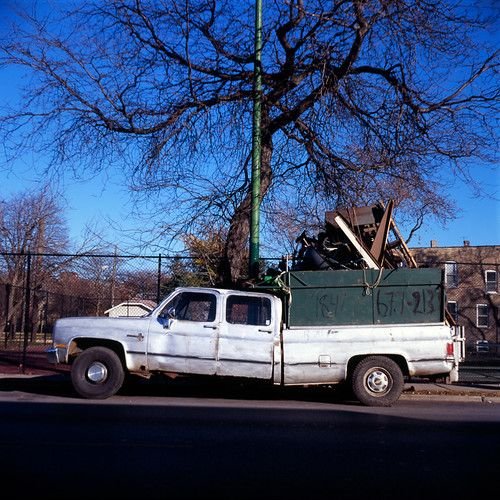
You would think the frame was bent bad with how low the rear of the cab is
I would fix it, but as I have plans to scrap the cab, and re-print it I see no real reason to bother.
I tried to take a better picture, but I couldn't get back far enough to get a better angle as I just threw it on my laser cutter for a quick pic. Woulda took it outside, but its been raining the past few days.
08-19-2024, 09:24 PM
#589
Join Date: Jul 2007
Location: North West Indiana
Posts: 12,861
Likes: 0
Received 20 Likes
on
19 Posts
Well I got the re-redesigned(3rd times the charm) e-mt ready for its 1st test with the new gearing method. I found an issue when assembling it to where the spur gear cover can't close due to it hitting another part so I just broke that part off, and will redesign it probably in a day or two, BUT it is able to run now, and I'll most likely test it in the afternoon. The current gearing is 22/85(or 90 I'm not sure) so this design should be the final version.
There is a chance I might have to reprint the mount though as I printed it out of plain old PLA which has a low deformation temperature. If it deforms I'll print it out of petg which will maintain its shape after something like 40-60 degrees (C) more heat before deforming. Basically made it out of PLA as I bought a spool kinda cheap(and this particular one glows in the dark >.> due to being on sale. This was already the 3rd or so reprint as the 1st few a few measurements were off by a few millimeters, or I made parts thicker to make them more rigid, or in the last major change I had to move the motor mount screw 5mm's towards the outside as it would be hitting the motor, and I had to cut a slot into the aluminum mount I made to accommodate it which made me extremely happy that I made that part way bigger then I designed it to be(the template was quite a bit smaller)
I'll post pics when I run it..
There is a chance I might have to reprint the mount though as I printed it out of plain old PLA which has a low deformation temperature. If it deforms I'll print it out of petg which will maintain its shape after something like 40-60 degrees (C) more heat before deforming. Basically made it out of PLA as I bought a spool kinda cheap(and this particular one glows in the dark >.>
due to being on sale. This was already the 3rd or so reprint as the 1st few a few measurements were off by a few millimeters, or I made parts thicker to make them more rigid, or in the last major change I had to move the motor mount screw 5mm's towards the outside as it would be hitting the motor, and I had to cut a slot into the aluminum mount I made to accommodate it which made me extremely happy that I made that part way bigger then I designed it to be(the template was quite a bit smaller)I'll post pics when I run it..
08-20-2024, 11:28 AM
#590
Join Date: Jul 2007
Location: North West Indiana
Posts: 12,861
Likes: 0
Received 20 Likes
on
19 Posts
Ran the E-mt for like 15 mins full throttle the motor hit 135 degrees (F), and this was through grass mostly so it had a lot of resistance as the grass wasn't that short. The torque that was added is kinda nuts as now the front end pulls ups a little.
Only reason I stopped the test was the dogbone that keeps popping out popped out, and bound up the wheel, and lost its spacers that it had.
But yea outside some minor issues with the spur/pinion gear cover (which is more of a fitment issue not mechanical) the design is done as the main parts work perfect, and the stuff aligns right.
Next to try it with tires off of the wheely king as I have a few laying around to give it some real height
Edit: I updated the post on the electric forum with more detail, and in doing so I realized I have to remake the mount out of PETG as the 135 degrees the motor hit is only 5 degree away from the temperature PLA(what it is made of) starts to deform, and melt. Whereas PETG is good till over 212 degrees which is way hotter then the motor ever should get to. Guess I should start dehydrating it so I could use it tomorrow. The fun of engineering things and having to take thermal load into play for material choice.
Edit 2 just realized I don't got enough PETG on the spool so this will have to wait till next time I order filament
Last edited by SyCo_VeNoM; 08-20-2024 at 11:57 AM.
The following users liked this post:
suburban_hooligan (08-20-2024)
 08-20-2024, 02:46 PM
#592
Join Date: Jul 2007
Location: North West Indiana
Posts: 12,861
Likes: 0
Received 20 Likes
on
19 Posts
Do it!
Hell till I started this project it was sitting in parts in multiple boxes since 2009 or 2010 or so. So its never too long to resurrect one
Truthfully I'm shocked that the tires are still good as they are tires that were stock on the truck from the 90's.
Hell till I started this project it was sitting in parts in multiple boxes since 2009 or 2010 or so. So its never too long to resurrect one
Truthfully I'm shocked that the tires are still good as they are tires that were stock on the truck from the 90's.
08-24-2024, 10:26 AM
#593
Join Date: Jul 2007
Location: North West Indiana
Posts: 12,861
Likes: 0
Received 20 Likes
on
19 Posts
after all these years I finally figured out why EVERY MT 1 I've owned kept throwing the front left(when looking from behind) dogbone. The cup from what I could measure is close to 2mm's(I couldn't get an exact measurement) closer to the center then the other side. I've always wondered why the fuel tube I put in the right side that made the dogbone sit perfect would still have the one fly out on the left it was a god damn design flaw all this damn time.
Looking at the MT2 manual the diff outputs have a completely different part number.
Edit: I see the MT2's dogbone has a bigger ball end(which is why it has the diff part number) I bought CVD's ages ago for the MT2, but never got them to fit as I was using MT1 diffs in mine, and never noticed the part # difference that and they hit the C-hub for some reason I swapped to the alum c-hubs I bought ages ago, and ground down the center a little so they no longer hit. Gonna order the MT2 diff cups to swap into the diff, and that should fix all my issues with the RC.
Last edited by SyCo_VeNoM; 08-24-2024 at 12:39 PM.
08-24-2024, 01:13 PM
#594
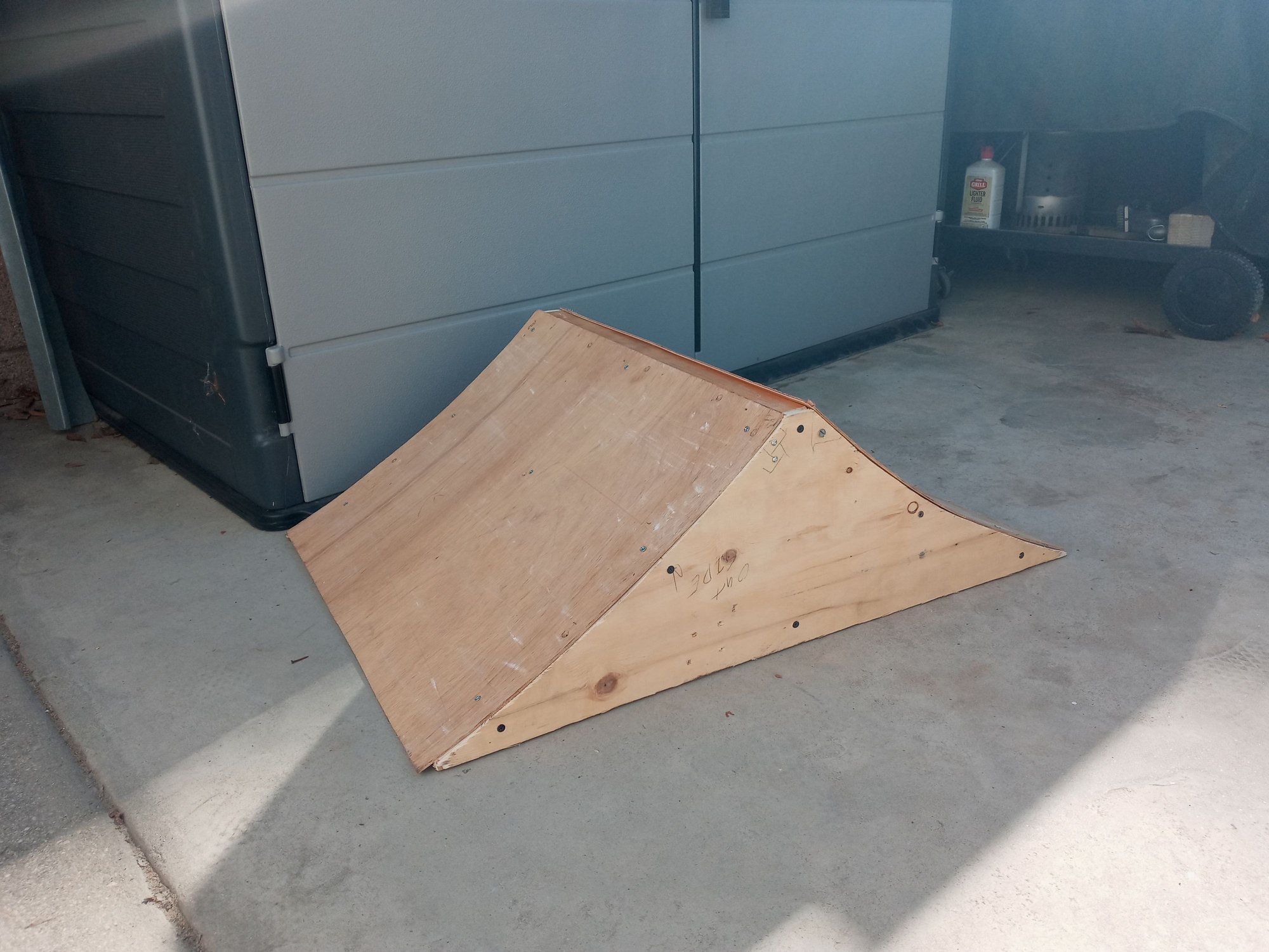
next weekend being a 3 day weekend im planning on doing some backyard bashing and i want some new obstacles. so im in the process of building a new spine ramp. nothing crazy, it's 10" tall, 32" long, and 24" wide so it's easy to hit.. just eyeballed and hand drew the curves so it'll launch the trucks far instead of high.
might build a small wedge ramp after this idk. might have enough wood.
might build a small wedge ramp after this idk. might have enough wood.
Last edited by suburban_hooligan; 08-24-2024 at 05:04 PM.
")
 08-27-2024, 01:22 PM
#597
Join Date: Jul 2007
Location: North West Indiana
Posts: 12,861
Likes: 0
Received 20 Likes
on
19 Posts
looks like it will be fun.
Makes me want to make a ramp
but for now I decided to fix up my HPI Recon. Last time I ran it was uhh 10ish years ago, and I broke 2 rims, and some other parts.
I remember I bought some aluminum after market parts for another RC that the Recon stole most the parts from put them on with a set of mini slash rims, and never ran it after. I put a new battery connector on it as it seems I used it for something else as it was missing along with a RX.
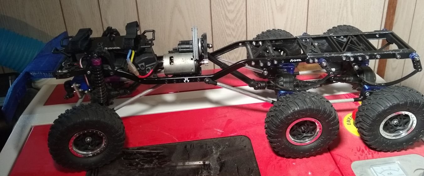
Today I also found a piece of c-channel I forgot I had from something I took apart that months ago that seems to fit perfectly over Axial's frames c-chanel which I am going to try to use to try and replace the 6X6 trucks brass tube frame that isn't all that good, not the straightest, and kinda flimsy. I will have to remake a few parts like the braces, but it will be way stronger, and better made. The c-channel piece was LITERALLY the perfect length as I cut it in half, and it is will be the same exact length to the back as the brass was to the millimeter.
Edit: Drilled the c-channel, and designed new brace parts for the center as the ones I had were made for the tube, and also made some spacers for the leaf spring shackles as I was using a pile of washers, and a nut. After taking the tube frame off the main frame I see just how bad it was. In some spots it was crushed in a bit throwing off its alignment. I was also shocked it didn't break yet with how many holes I drilled into it as at one spot there was not much holding it together still. Also the holes are spaced exactly the same now as I drilled one piece of the c-channel, and taped the other to it, and used the 1st sides holes as a guide to drill the other(also the holes were a little small I initially drilled). The prior tube frame the holes were not as precisely mirrored on the 2 sides as I kind of drilled the while they were on the frame so some were a bit off, and used a piece of paper to map the spots >.>.
Makes me want to make a ramp
but for now I decided to fix up my HPI Recon. Last time I ran it was uhh 10ish years ago, and I broke 2 rims, and some other parts.
I remember I bought some aluminum after market parts for another RC that the Recon stole most the parts from put them on with a set of mini slash rims, and never ran it after. I put a new battery connector on it as it seems I used it for something else as it was missing along with a RX.
Today I also found a piece of c-channel I forgot I had from something I took apart that months ago that seems to fit perfectly over Axial's frames c-chanel which I am going to try to use to try and replace the 6X6 trucks brass tube frame that isn't all that good, not the straightest, and kinda flimsy. I will have to remake a few parts like the braces, but it will be way stronger, and better made. The c-channel piece was LITERALLY the perfect length as I cut it in half, and it is will be the same exact length to the back as the brass was to the millimeter.
Edit: Drilled the c-channel, and designed new brace parts for the center as the ones I had were made for the tube, and also made some spacers for the leaf spring shackles as I was using a pile of washers, and a nut. After taking the tube frame off the main frame I see just how bad it was. In some spots it was crushed in a bit throwing off its alignment. I was also shocked it didn't break yet with how many holes I drilled into it as at one spot there was not much holding it together still. Also the holes are spaced exactly the same now as I drilled one piece of the c-channel, and taped the other to it, and used the 1st sides holes as a guide to drill the other(also the holes were a little small I initially drilled). The prior tube frame the holes were not as precisely mirrored on the 2 sides as I kind of drilled the while they were on the frame so some were a bit off, and used a piece of paper to map the spots >.>.
Last edited by SyCo_VeNoM; 08-27-2024 at 07:35 PM.
08-29-2024, 12:24 PM
#598
Join Date: Jul 2007
Location: North West Indiana
Posts: 12,861
Likes: 0
Received 20 Likes
on
19 Posts
well made all the parts for the 6X6 truck. I had to redo the rear leaf spring mounts as the brass tube rails were farther in so the leaf springs were pushing out, and also I couldn't fit the bed on it anymore so I made them thinner there is like 1mm of space on each side of the screws now.
I painted the rails with black primer, but most it wore off. I'm guessing it didn't get a good bond to it not like it matters at it isn't going to be seen anymore as the bed is going to cover it up completely.
I painted the rails with black primer, but most it wore off. I'm guessing it didn't get a good bond to it not like it matters at it isn't going to be seen anymore as the bed is going to cover it up completely.
Last edited by SyCo_VeNoM; 08-29-2024 at 12:53 PM.
The following users liked this post:
suburban_hooligan (08-29-2024)
09-01-2024, 11:56 AM
#599
just mowed my backyard. cut the grass short so i can drive on it without heat issues. currently doing a little "art work" on the new ramp, then ill charge up a pack and finally test it out.
09-01-2024, 06:40 PM
#600
Join Date: Jul 2007
Location: North West Indiana
Posts: 12,861
Likes: 0
Received 20 Likes
on
19 Posts
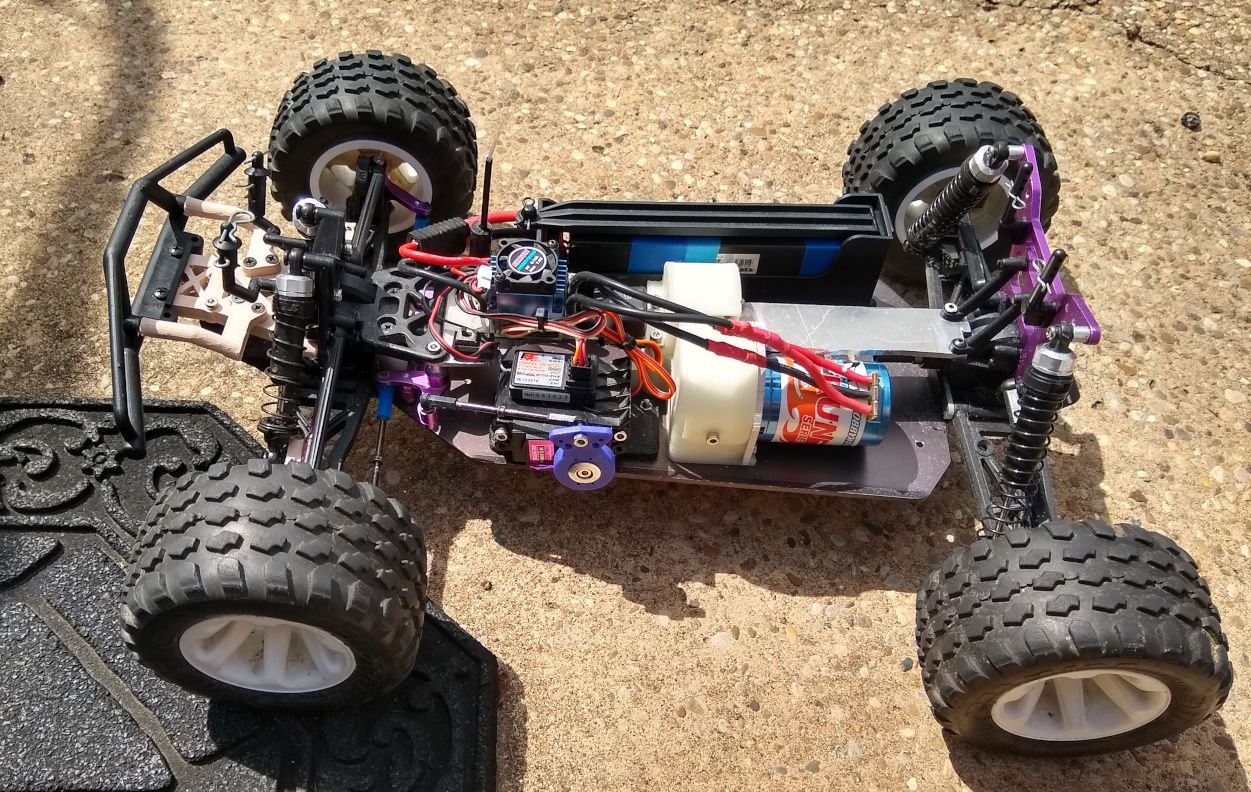
just finished redesigning my Jammin X1 CRT a little bit that was converted to electric years ago.
Made a new esc mounting plate as the hobbywing ESC I changed to didn't fit where the old ESC that I sold was.
I honestly can't believe it took me over an hour to make the stuff fit, and run the wires >.>
If the weathers good tomorrow I might take it outside for a run, and hope my old ass batteries don't blow